25
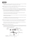
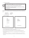
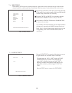
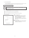
Select INPUT TEST to have the screen shown below appear and to observe the status of each switch and the
value of each V.R. on the Control Panel. Periodically check the status of each switch and V.R. on this screen.
7 -4 INPUT TEST
FIG. 7.4 INPUT TEST
By pressing each switch, if the display on the right-hand side
of the name of each switch changes to ON from OFF, the SW
and the wiring connections are satisfactory.
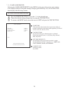
To check CHUTE 1 & CHUTE 2 coin switches, open the
COIN CHUTE DOOR and insert a coin(s) in the slot.
Press either the TEST BUTTON and the START BUTTON
to return to the test menu.
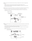
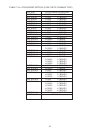
As a standard, refer to the following for each of the Volume’s
adjustment. By operating the Handle (Steering Wheel) and
Pedal, if the V of each Volume guage smoothly moves as the
corresponding value varies ina natural manner, then it is
satisfactory.
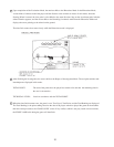
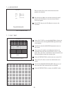
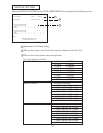
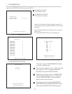
Choose OUTPUT TEST to cause the following lower screen
to appear. In this test, check the status of each lamp.
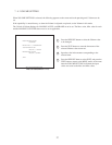
The right-hand side “ON” & “OFF” display of START
LAMP automatically alternates. The lamp lights up
when “ON” is displayed and goes off when “OFF” is
displayed. Check to ensure that the lamp lights up and
goes off in consistency with the display of “ON” and
“OFF”.
Press the TEST button to return to the TEST MENU.
FIG. 7.5 OUTPUT TEST
7 - 5 OUTPUT TEST
OUTPUT TEST
START LAMP OFF
>EXIT
PRESS TEST BUTTON TO EXIT
INPUT TEST
COIN CHUTE #1 OFF
COIN CHUTE #2 OFF
SERVICE OFF
TEST OFF
START OFF
LEVER UP OFF
LEVER DOWN OFF
HANDLE 7bH
ACCEL 3fH
BRAKE 33H
PRESS TEST AND SERVICE BUTTON TO EXIT


