


4
OPERATION
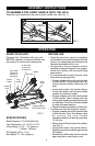
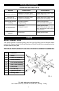
KNOW YOUR JACK
Compare Fig. 2 illustration with your jack
BEFORE operation to become familiar with
the location of various jack components.
SPECIFICATIONS
Rated Capacity: 2-1/4 Ton/4500 Lbs
Jack Dimensions: 21” x 8-1/2” x 5-1/2”
Lifting Range: 5-1/2” ~ 15” (Approx.)
(140mm - 381mm)
Oil Capacity: 90 cc ± 5 cc
Net Weight: 27.1 lbs. (Approx.)
BEFORE USE
•Read the operator's manual completely
and familiarize yourself thoroughly with the
product, its components and recognize the
hazards associated with its use.
•Occasionally during shipment and/or
handling air can get trapped in the system,
which can interfere with the jacks lifting
performance.
• It is recommended to cycle the jack a few
times without applying load:
• Engage release valve with notched end
of jack handle. Close release valve by
turning the jack handle clockwise until
tight.
• Insert jack handle into handle sleeve.
Pump the handle until the jack saddle
reaches its maximum height.
• Engage release valve with notched end
of jack handle. Open release valve by
turning jack handle counterclockwise, but
no more than 1/2 full turn. Allow the saddle
to reach its lowest position.
• Repeat the above procedure a few times.
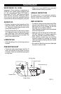
•To release air from the hydraulic system:
• Engage release valve with notched end
of jack handle. Open the release valve
by turning the jack handle
counterclockwise, but never by more than
1/2 full turn.
• Remove the oil filler plug from the cylinder.
(see Fig. 3)
• Insert jack handle into handle sleeve.
Rapidly pump jack handle through several
full strokes.
• Reinstall the oil filler plug into the cylinder
again and jack is now ready to use.
FIG. 2
front
wheel
saddle
lifting arm
jack handle
handle
sleeve
cover plate
(remove to
access oil
filler plug)
frame
base
release
valve
castor
oil filler plug
(not shown,
on reservoir)
engage release
valve with this end
carry
handle
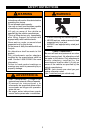
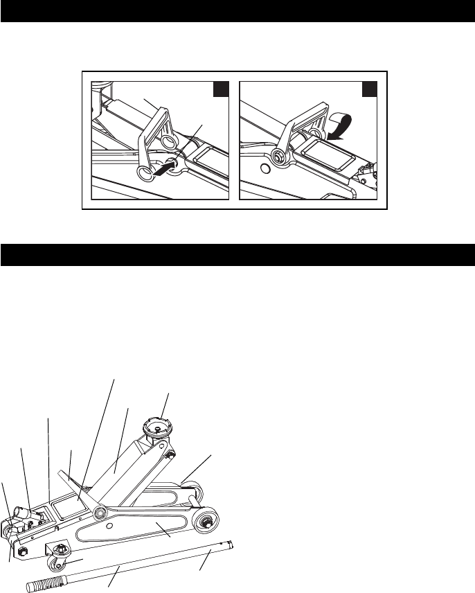
ASSEMBLY INSTRUCTIONS
TO ASSEMBLE THE CARRY HANDLE ONTO THE JACK
Snap the carry handle onto the nuts of jack’s middle axle. (see Fig. 1)
FIG. 1
1 2
Nut of
middle axle
Carry handle