


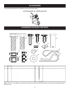


5
3/8-16 x 1"
CARRIAGE
BOLT
3/8" NYLOCK NUT
LIFT LEVER
ASSEMBLY
SLEEVE HITCH FRAME
LEFT PIVOT BRACKET
RIGHT PIVOT BRACKET
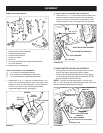
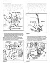
FOR ALL TRACTORS
• Place the Left Pivot Bracket onto the end of the Lift
Lever Assembly (the Right Pivot Bracket comes
al ready installed on the assembly). See fi gure 3.
• Attach the Right and Left Pivot Brackets to the Sleeve
Hitch Frame As sem bly using four 3/8" x 1" carriage
bolts and 3/8" nylock nuts. See fi gure 3.
FIGURE 3
FIGURE 5
5/8"x 2"
HEX BOLT
5/8" NYLOCK NUT
5/8" JAM NUT
5/8"x 1-3/4"
HEX BOLT
LIFTING LINK
FIGURE 4
LIFT LEVER
ASSEMBLY
SLEEVE HITCH
FRAME ASSEMBLY
WELD
PIN
5/8" NYLOCK NUT
SPACER PLATE
(SEE NOTE)
HEX BOLT
5/8" x 1-3/4"
• Attach the Sleeve Hitch Lift Assembly to the Sleeve
Hitch Frame Assembly using three 5/8" x 1-3/4" clevis
pins and 3/32" hair cotter pins as shown in fi gure 6.
• Install the Hitch Pin in the sleeve hitch and secure it
with the 5/32" hair cotter pin. See fi gure 6.
FIGURE 6
(3) 3/32" HAIR
COTTER PINS
5/32" HAIR
COTTER PIN
HITCH PIN
(3) CLEVIS PINS
• Assemble the two 5/8" jam nuts halfway onto the two
5/8" x 2" hex bolts. Screw the bolts into the nuts that
are welded to the Sleeve Hitch Lift As sem bly. Tighten
the jam nuts against the welded nuts. See fi gure 5.
• Assemble the Lifting Link to the Sleeve Hitch Lift
Assembly using a 5/8" x 1-3/4" hex bolt and a 5/8"
nylock nut. Use the bottom hole in the Lifting Link
(gives the lowest implement depth setting). Tighten the
nut only until snug. Do not squeeze the welded arms
together. See fi gure 5.
• Hook the Sleeve Hitch Frame As sem bly onto the weld
pins in the mounting brack ets. Attach the bottom of the
Assembly to the trac tor hitch using a 5/8" x 1-3/4" hex
bolt and a 5/8" nylock nut. See fi gure 4.
NOTE:
If your tractor hitch has ridges that prevent the
sleeve hitch assembly from resting fl at, place the spacer
plate underneath the sleeve hitch assembly.