


Astra 1000RS - Page 13
independent left and right parking light circuits, diodes must be installed to keep the circuits
separate. NOTE: Do not connect the WHITE wire to the vehicle’s headlight circuit.
Pin 16 RED WIRE: Module Power Input (+). Connect to a constant source of +12V.
2-Pin Blue Connector: Valet switch port. Mount switch where it is accessible from the driver’s
position.
2-Pin Red Connector: LED port. Mount LED where it may be easily seen from either side of the
vehicle.
3-Pin White Door Lock Connector: Door lock port.
· BLUE WIRE - negative unlock output (-) 500mA.
· RED WIRE - (+) 100mA trigger output for optional plug-in door lock relay module,
· GREEN WIRE - negative lock output (-) 500mA.
5-Pin White Flat Connector: Antenna connector port.
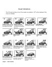
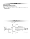
Starter doesn’t start and Side Lights flash:
3 Times - Hood Trigger is active
4 Times - Brake Lights stay On
5 Times - Unit is in Valet (service) mode, and start is disabled.
6 Times - Handbrake Off (manual transmission Mode Only).
7 Times - Start sequence not initiated (manual transmission Mode Only).
Starter
Diagnostics