40
S4359146
4. HOW TO INSTALL THE OUTDOOR UNIT
4-1. Removing the Protective Spacer for
Transportation
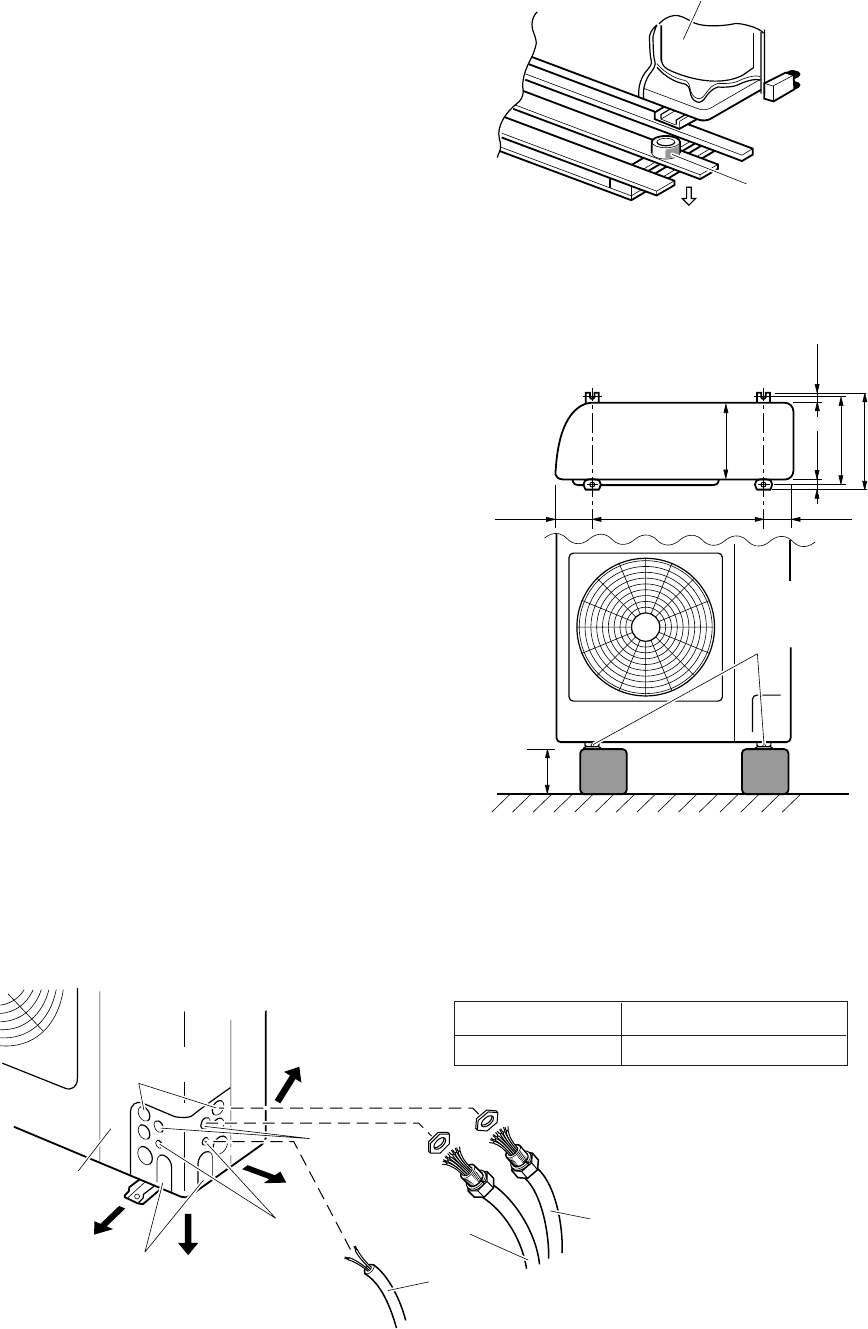
Remove the packing skid from the bottom of unit and
then remove the plastic spacer used to secure the
compressor during transportation. (Fig. 4-1)
Place the unit on a level concrete pad, block or equal
and anchor.
Refer to Section 2. “Selecting the Installation Site”.
4-2. Installing the Outdoor Unit
(1) Install blocks or a solid platform under the out-
door unit which provides a minimum height of
6 in. from ground level. (Fig. 4-2)
(2) The outdoor unit must be bolted down tightly to
the blocks or platform with 4 anchor bolts.
4-3. Tubing Direction
● Tubing can be extended in 4 different directions as
shown in Fig. 4-3.
● Service valves are housed inside the unit. To access
them, remove the access panel by removing the 3
attaching screws, then slide the panel downward
and pull it toward you.
If either rear, right or front tubing is needed, punch
out the knockout holes with a hammer or similar tool.
● After punching out the knockout holes, mount
plastic protectors on the tubing outlets. These
accessories are packed inside the unit and can be
accessed through the access panel.
● Use tube benders to extend refrigerant tubing to the
outside.
Compressor
Plastic spacerPacking
skid
0496_C_
I
Fig. 4-1
Fig. 4-2
Fig. 4-3
Connector Size
Power Supply Inter-unit Power Line
1/2" 1/2"
Access panel
Front
Tubing
outlets
Control
wiring
outlets
Down
Right
Rear
1102_C_I
Inter-unit
wiring outlets
Power supply
wiring outlets
Power
supply line
Inter-unit
power line
Inter-unit
control line
1168_C_I
6-11/16 26 4-21/64
Anchor
bolts
(not supplied)
Height :
Min: 6 in.
1-3/16 1-3/16
15-3/4
14-31/32
13-3/8
Unit: inch


