7
S4359146
99
99
9
SC
11
11
1
X
88
88
8
WT
77
77
7
RC
(WL)
55
55
5
C
44
44
4
U
33
33
3
T
22
22
2
K
66
66
6
RC
(WD)
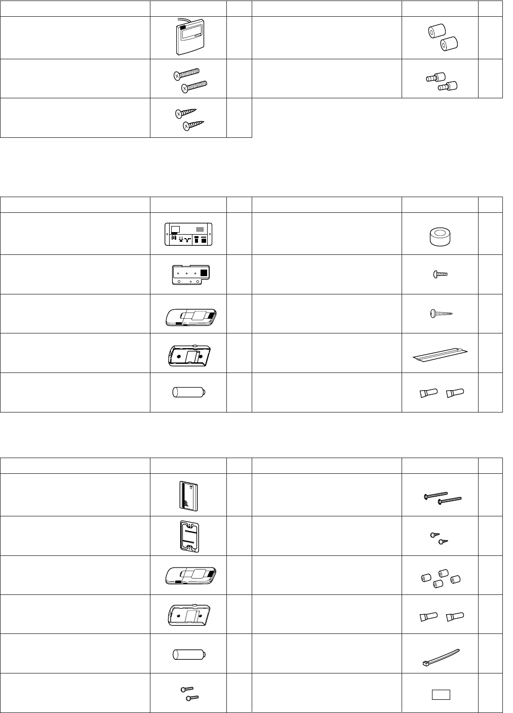
Table 1-6 (Accessories for the Wired Remote Controller)
Part Name Figure
Q’ty
Part Name Figure
Q’ty
1 Spacers 2
2 Wire joints 4
Wood screws 2
Table 1-7 (Accessories for the Wireless Remote Controller)
<RCS-SH80UA.WL>
Part Name Figure
Q’ty
Part Name Figure
Q’ty
Operation controller 1 Spacers 2
Indicator section 1 4
Wireless remote controller 1 2
13
Batteries 2 Wire joints 4
Wired remote controller
(comes with 7-7/8 in. wire)
Pan-head tapping screws
4 × 13/32 in.
Truss-head tapping screws
4 × 5/8 in.
Run Timer
Heating preparations
Machine screws
M4 × 1 in.
Vinyl clampers
L 5-29/32
Small screws
M4 × 1-9/16 in.
Machine screws
M4 × 1 in.
Ceiling installation paper pattern
(
3-3/4 × 2-1/32 in.
)
<RCS-BH80UA.WL>
Part Name Figure
Q’ty
Part Name Figure
Q’ty
12
Carrier for ceiling installation 1 Wood screws 2
Wireless remote controller 1 Spacers 4
1 Wire joints 4
Batteries 2 Clamper 1
21
Separate type signal receiving unit
(comes with 7-7/8 in. wire)
Wireless remote controller
mounting cradle
Wireless remote controller
mounting cradle


