


RoyalTek Confidential 14
REB-1315LPNX Operational Manual
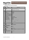
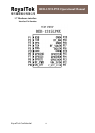
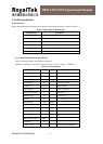
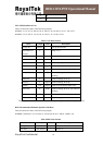
Bias voltage
18
GND G Ground Reference Ground
19
RF_IN I GPS Signal
input
50 Ω @1.57542GHz
20
GND G Ground Reference Ground
21
GND G Ground Reference Ground
22
GND G Ground Reference Ground
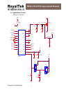
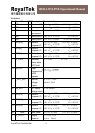
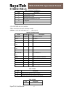
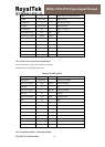
VIN_3V3(+3.3V DC power Input)
This is the DC power supply input pin for GPS system. It provides voltage to module.
GND
GND provides the reference ground.
Boot
Set this pin to high for programming flash.
RXA
This is the main receiver channel and is used to receive software commands to the board from
SIRFdemo software or from user written software.
RXB
This is the auxiliary receiving channel and is used to input differential corrections to the board
to enable DGPS navigation. (Default Null).
TXA
This is the main transmitting channel and is used to output navigation and measurement data
to SiRFdemo or user written software.
TXB
For user’s application (not currently used). (Default Null).
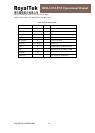
RF_PWR
This pin indicates state of RF voltage.
RF_IN
This pin receives GPS analog signal. The line on the PCB between the antenna(or antenna
connector) has to be a controlled impedance line (Microstrip at 50Ω).
RF_VOUT
This pin can provide maximum power 30mA@2.85V for active antenna.
PPS
This pin provides one pulse-per-second output from the board, which is synchronized to GPS
time. This is not available in Trickle Power mode.