


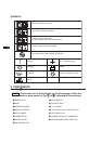

JP
US
GB
DE
FR
NL
ES
IT
PT
GR
NO
SE
FI
DK
RU
CN
AR
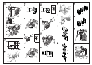
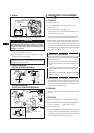
1. STARTING
(1) Open the fuel cock.
(2) Turn the STOP SWITCH to the position “
I
” (ON).
(See Fig.3
q)
(3) Close the choke lever. (See Fig.3
w)
If the engine is cold or the ambient temperature is low,
close the choke lever fully.
If the engine is warm or the ambient temperature is high,
open the choke lever half-way, or keep it fully open.
(4) Pull the starter handle slowly until resistance is felt. This
is the “compression” point. Return the handle to its
original position and pull swiftly. Do not pull out the rope
all the way. After starting the engine, allow the starter
handle to return to its original position while still holding
the handle. (See Fig.3
e)
5. OPERATING YOUR ENGINE
(See Fig.
33
33
3)
2. RUNNING
After the engine starts, warm it up without load for a few
minutes.
3. STOPPING
(1) Allow the engine to run for 1 or 2 minutes before stopping.
(2) Turn the STOP SWITCH (or KEY SWITCH) counterclock-
wise to the position “ ” (OFF). (See Fig.4
q)
(3) Close the fuel cock.
(4) Pull the starter handle slowly and return the handle to its
original position when resistance is felt. This operation
is necessary to prevent outside moist air from intruding
into the combustion chamber. (See Fig.4
w)
(5) After starting the engine, gradually open choke by turning
the choke lever and finally keep it fully opened. Do not
fully open the choke lever immediately when the engine
is cold or the ambient temperature is low, because the
engine may stop. (See Fig.3
r)
FOR ELECTRIC STARTER MODELS.
Insert the key into the key slot and set it at the “ I ” (ON)
position. Turn it to the right (START position) to start the
engine. (See Fig.3
e)
Do not operate the electric starter continuously for
more than 5 secounds, even if the engine dose not
start.
If the engine failed to start, set the key to the “ I ”
(ON) position and wait for about 10 secounds before
retrying.
Never turn the key switch to the START position while
engine is running.
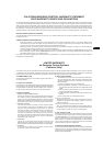
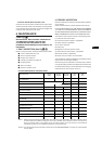
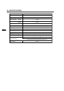
5. WIRING DIAGRAM
(RECOIL STARTER MODELS)
(2) Ground negative terminal of the battery to the engine
body or machine with ground wire.
(3) When installing the key switch on the machine, install
with its drain hole at the bottom.
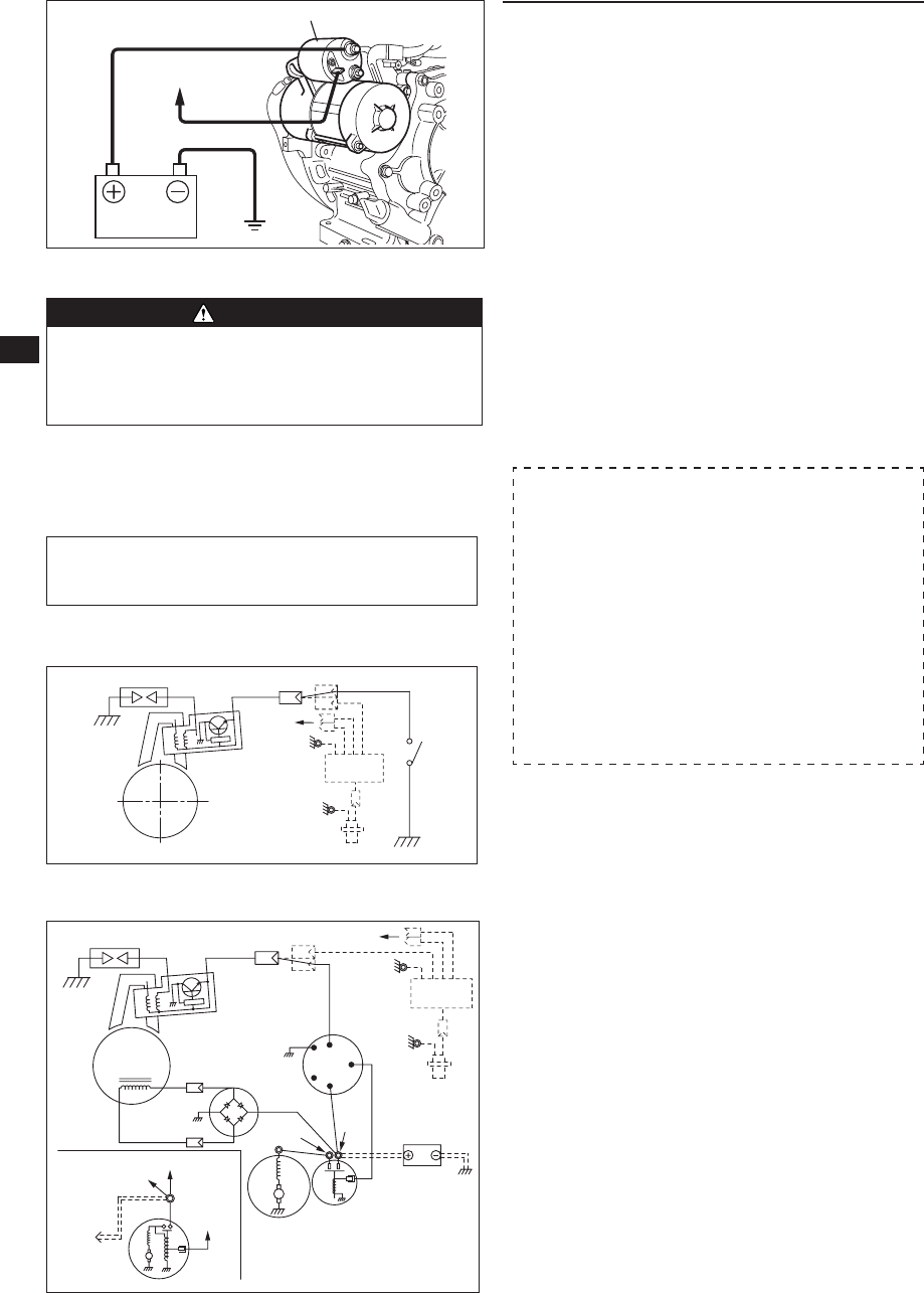
WIRING DIAGRAM
(ELECTRIC STARTER MODELS)
Optional hardware shown by dotted lines.
NOTE
Tighten bolts and nuts on terminals securely so that they
will not be loosened by vibration.
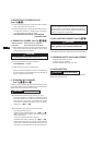
4. WIRING
To Key switch
(ST)
To Key switch (B)
To Diode rectifier
EX30
To Battery
LA108
LA408
Spark plug
Black
+M
-
M
ST
B
AC
LA106
LA406
LA306
Charge coil
Magneto
Electric starter
Magnetic switch
Key switch
To LED Lamp
Oil sensor
Oil sensor
control unit
Battery
Diode
rectifier
Ignition coil
Electric
starter
Spark plug
Black
Stop switch
Ignition coil
Flywheel
To LED
Lamp
Oil sensor
Oil sensor
control unit
BATTERY
To KEY SWITCH
(TERMINAL "ST")
CABLE
EARTH WIRE
MAGNETIC SWITCH
(1) Connect positive (+) terminal of the magnetic switch and
positive (+) terminal of the battery with battery cable.
Make sure the polarity of battery terminals. Never connect
the
battery cable with the battery negative (-) terminal.
When connecting the battery cable with the battery negative
(-)
terminal, diode rectifier chips will be burned out or
damaged in a moment.
CAUTION