


-
37
-
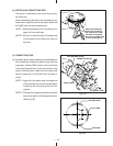
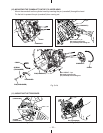
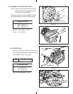
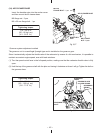
(15) VALVE CLEARANCE ADJUSTMENT
Temporarily fit the flywheel.
Rotate the crankshaft up to the compression top
dead center and inser t the thickness gauge
between the valve and the adjusting screw of
rocker arm to measure the clearance.
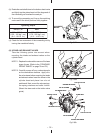
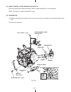
[Adjustment method]
Loosen the nut on the adjustment screw and turn
the screw to adjust the valve clearance. When
the valve clearance is correct, tighten the nut.
Fig. 5-46
Fig. 5-47
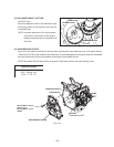
ROCKER ARM
(INTAKE VALVE SIDE)
THICKNESS GAUGE
ROCKER ARM
(EXHAUST
VALVE SIDE)
ADJUSTMENT
SCREW
NUT
Fig. 5-45
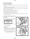
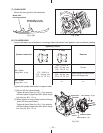
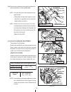
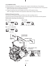
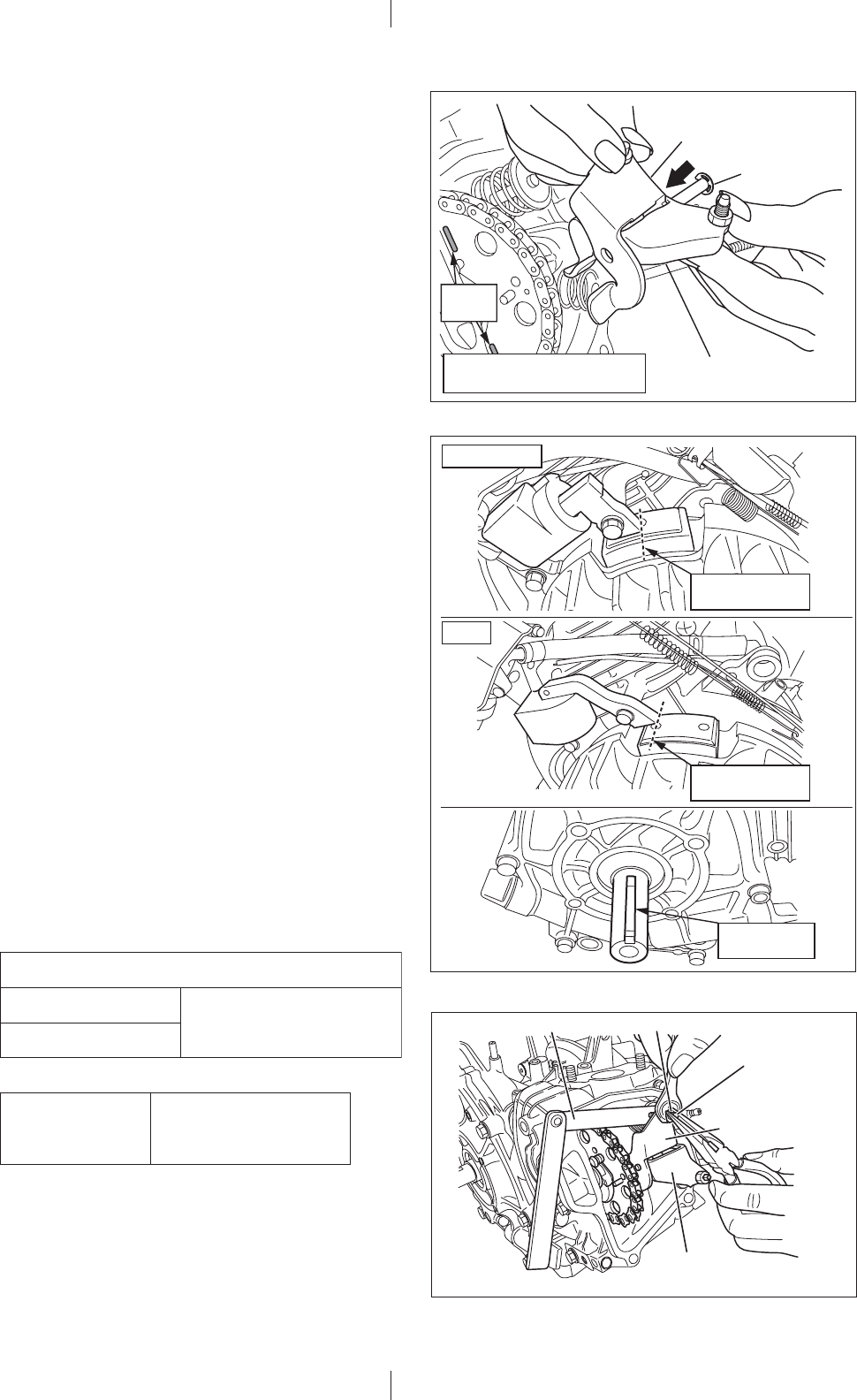
(14) Pass the pin (rocker arm) through the rocker arm
and mount them on the cylinder head.
NOTE 1:
Conduct this job at the compression top
dead center.
(The position of two punch marks on cam
sprocket is in parallel with the cylinder
head surface at a time.)
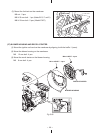
NOTE: After adjusting the valve clearances, rotate
the crankshaft and check again that the
intake and exhaust valve clearance are
correct.
Valve clearance (when the engine is cold)
Intake valve side
Exhaust valve side
Tightening
torque
5.0 - 7.0 N m
(50 - 70 kgf cm)
(3.6 - 5.1 ft lb.)
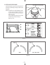
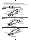
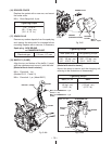
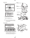
EX13, 17, 21
EX27
The position of
top dead center
The key way
is at the top
The position of
top dead center
0.12 mm
(0.0047 in.)
+0.0012
0
+0.03
0
NOTE 2:
Make sure that the piston is at the
compression top dead center by checking
mutual position between the flywheel and
the ignition coil or by checking that the
key way is at the top.
(See each Fig.5-46)
ROCKER ARM
(INTAKE VALVE SIDE)
ROCKER ARM
(EXHAUST VALVE SIDE)
PIN
(ROCKER ARM)
The position of compression
top dead center
Punch
marks