


-
53
-
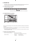
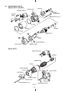
9. ELECTRIC STARTER
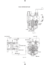
9-1 SPECIFICATIONS
Models EX17, 21 Model EX27
Voltage (V) 12
Power (kW) 0.6 0.6
Weight (kg) 1.6 3.4
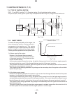
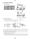
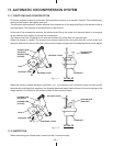
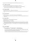
9-2 OPERATING PRINCIPLES
The battery is connected to the 6 or 8 mm diameter terminal of the magnetic switch.
The figure below shows the state when the starter is ON.
There are two energized circuits: the magnetic switch (M) circuit and the starter motor (S) circuit. When the key
switch is ON, the (M) circuit is closed, the current flows in the direction of the arrows, the coil of the magnetic
switch is magnetically excited and the contactor is pulled.
As a result, a low current flows through the (M) circuit and a high starter current flows through the (S) circuit.
This energizes the starter motor and cranks the engine.
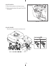
Engagement of the pinion gear (EX17,21)
When the starter motor is started, the weight built into the spiral splines located on the shaft moves in the direction
of the axis driven by centrifugal force and pushes out the pinion gear, and the pinion gear engages the ring gear.
Fig. 9-1
SS
M
M
M
M
M
ELECTRIC STARTER
MAGNETIC
SWITCH
KEY SWITCH
BATTERY
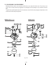
Fig. 9-2
EX 17, 21
EX 27
Pinion ge
ar
129.5
PINION GEAR
157.8