(2)
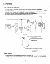
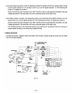
At lower engine revolution, when the flywheel reached the ignition point the low speed ignition timing
control circuit operates to run the base current
13
to turn the signal transistor
A
"ON"
allowing the
current
I1
to
bypass
as current
14.
At this moment the power transistor
turns
"OFF"
and the current
h
is abruptly shut resulting in the high
voltage generated in the secondary coil which produces
sparks
at the
spark
plug.
(3)
At higher engine revolution, the advancing control circuit operates at the ignition timing to
run
the
base current
IS
to turn the signal transistor
B
"ON"
allowing the current
11
to bypass as current
16.
At this moment the power transistor turns
"OFF"
and
the current
L
is
abruptly shut resulting
.in
the high
voltage generated in the secondary
coil
which produces sparks at the spark plug.
The operating timing
of
the advancing control circuit advances in accordance with the increase
of
'
engine speed resulting
in
the advancing
of
ignition timing.
*
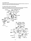
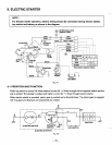
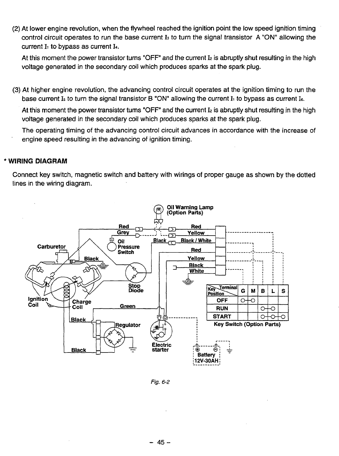
WIRING
DIAGRAM
Connect
key
switch, magnetic switch and battery with wirings
of
proper gauge
as
shown
by
the dotted
lines
in
the wiring diagram.
Fig.
6-2
-
45-


