


GPS Receiver Board GPS-24 / 24A Operating Manual
Rikaline
Specifications subject to change without prior notice
Rikaline International Corp. 10F, 64, Kang-Din Road, Taipei 108, Taiwan
Tel: ++886 2 2370 4688 Fax: ++886 2 2370 4686 E-Mail: info@rikaline.com.tw Web: www.rikaline.com.tw
Field Format Min
chars
Max
chars
Notes
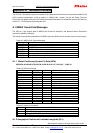
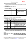
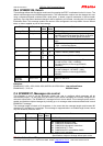
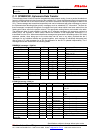
Message ID $PNMRX112 6 8 PNMRX112 protocol header.
Operating Mode Into 1 1 0 = Fully Active
1 = LDCM1
OFF period Into 1 2 RF off time in seconds [5:10]
Checksum *xx (0) 3 3 2 digits.
Message
terminator
<CR> <LF> 2 2 ASCII 13, ASCII 10.
Examples:
$PNMRX112, 1, 5*xx: enable low power mode (with 5 seconds off time between 2 fixes)
C.9 $PNMRX113, GPS Core Activity Control
This message is used to disable GPS Core activities (data extraction and fix generation) on the node. The
goal of this message is to disable these two functions when they need to be overwritten by external values
for test purpose. A reset message must be set after the PNMRX113 in order to resume operation. For
instance if a different almanac needs to be downloaded to the receiver then, data extraction must be
disabled, then the new almanac can be downloaded. A reset command will then be used to restore operation
with hen new almanac.
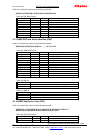
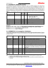
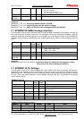
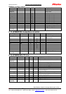
Field Format Min
chars
Max
chars
Notes
Message ID $PNMRX113 6 8 PNMRX113 protocol header.
Checksum *xx (0) 3 3 2 digits.
Message
terminator
<CR> <LF> 2 2 ASCII 13, ASCII 10.
Examples:
$PNMRX113*xx: Stops GPS Core activities.
C.10 $PNMRX300, Almanac Data Transfer
This message format is used to transfer the almanac data between nodes; it uses a packed hexadecimal
format to transfer almanac data for each of the available SV’s. Since the Almanac data is large and can take
time to transfer over a slow serial interface, the data is divided into individual messages for each of the SV’s.
These messages are transmitted sequentially and can be interleaved with other messages to prevent the
Almanac data blocking higher priority messages such as scheduled PVT information. The data for these
messages is expressed as signed or unsigned fixed point values which have been scaled from the floating
point values used in the position solution. The appropriate scaling factors are included in the table. There is
1 message for each satellite for which data is available. When transmitted these messages are generated in
ascending order of SV Id, when being sent to the node these can be sent in any order, each message is
individually interpreted and processed.
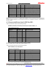
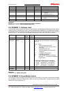
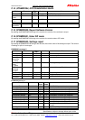
Field Format width scale Notes
Message ID $PNMRX300 8 PNMRX300 protocol header.
SV Id Int 2 Decimal Satellite vehicle Id from 1 to 32.
e Hex 4 2
-21
16 bit signed int, scale.
Health Hex 2 Bitmap of satellite health.
T
oa
Hex 2 Week Number
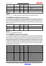
δ
i
Hex 4 2
-19
16 bit signed int.
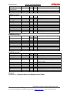
Omega dot Hex 4 2
-38
16 bit signed int.
Root_A Hex 6 2
-11
24 bit unsigned int.
Omegazero Hex 6 2
-23
24 bit signed int.
Perigee Hex 6 2
-23
24 bit signed int.
Mean Hex 6 2
-23
24 bit signed int.
Mean anomaly Hex 6 2
-23
24 bit signed int.
af0 Hex 6 2
-20
11 bit signed int.
af1 Hex 6 2
-68
11 bit signed int.
Checksum *xx (0) 3 2 digits.