


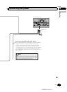
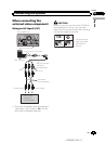
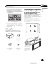
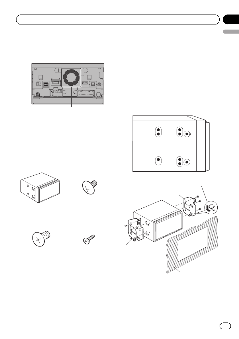
! The cords must not cover the area shown
in the figure below. This is necessary to
allow the amps and navigation mechanism
to dissipate heat.
Do not cover this area.
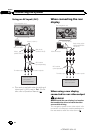
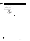
! The semiconductor laser will be damaged
if it overheats, so don’t install the naviga-
tion unit anywhere hot — for instance, near
a heater outlet.
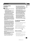
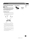
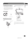
Parts supplied
Parts marked (*) are supplied with AVIC-
X950BH, AVIC-X850BT and AVIC-X8510BT.
The navigation unit Truss head screw
(5 mm × 8 mm)
(6 pcs.)
Flush surface screw
(5 mm × 9 mm)
(6 pcs.)
Screw*
(2 mm × 4 mm)
(1 pc.)
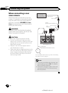
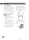
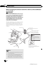
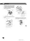
Installation using the screw holes
on the side of the navigation unit
% Fastening the navigation unit to the
factory radio-mounting bracket.
Position the navigation unit so that the brack-
ets screw holes and its screw holes are
aligned, and tighten the screws at three loca-
tions on each side.
Use either the truss head screws (5 mm ×
8 mm) or flush surface screws (5 mm ×
9 mm), depending on the shape of the brack-
et’s screw holes.
If the pawl interferes with installation,
you may bend it down out of the way.
Dashboard or console
T
russ head screw or
flush surface screw
Be sure to use the
screws supplied
with this navigation
system.
Factory radio-mounting bracket
<CRD4697-A/N>21
En
21
English
Section
03
Installation