AVIC-F500BT
<KKYZX> <08F00000> AU,EW,RE,UC
<F500BT_CONNECTION>
Издано Pioneer Corporation.
Авторские права ©sw 2008 Pioneer
Corporation.
Все права защищены.
Publié par Pioneer Corporation.
Copyright © 2008 par Pioneer Corporation.
Tous droits réservés.
Published by Pioneer Corporation.
Copyright © 2008 by Pioneer Corporation.
All rights reserved.
Connection diagram
Diagramme de connexion
Схема подключения
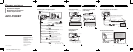
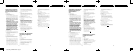
Connecting the car navigation system
10. REVERSE-GEAR SIGNAL INPUT (Violet/white)
(Refer to Connecting the reverse signal and parking brake leads.)
9. PARKING BRAKE (Light green)
(Refer to Connecting the reverse signal and parking brake leads.)
50 cm (1 ft. 8 in.)
50 cm (1 ft. 8 in.)
1.5 m (4 ft. 11 in.)
1.5 m
(4 ft. 11 in.)
20 cm (7-7/8 in.)
20 cm (7-7/8 in.)
2 m (6 ft. 7 in.)
1. Microphone
(CD-VM1) (sold separately)
2. This product
3. Cradle
4. Cable (supplied)
5. Vehicle power charger
To protect your product against sudden surges
in current, connect the vehicle power charger
only while the ignition switch is turned off.
7. Black
6 . DC 5V (Black)
8. To in-vehicle power
port socket
11. AMP CONTROL (Blue/white)
12. Not used.
13. Audio output (Left, Right) (Black)
Use the terminal when you want to output
the sound to external equipment.
15. Battery cable (Yellow)
This terminal is on the North American
model only.
Be sure to connect this lead to terminal
always supplied with power regardless
of ignition switch position.
16. Rear view camera input (Brown)
(Refer to When connecting a rear view camera.)
2 m (6 ft. 7 in.)
14. Fuse holder
(Fuse: 1 A)
Fig. 1 Abb. 1 Afb. 1 Рис.1
English
En
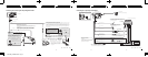
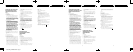
Connecting the iPod
6. USB interface cable
for iPod (CD-IU200VM)
(sold separately)
1. This product
2. Mini-USB port
3. iPod
®
4. AV IN
For details concerning operations and
compatibility, refer to “Operation Manual”.
Note
5.
Fig. 2 Abb. 2 Afb. 2 Рис.2
Connecting the USB
storage device
1. This product
3. USB storage device
(sold separately)
4. USB cable (supplied)
Connect an appropriate USB storage device.
2. Mini-USB port
2 m (6 ft. 7 in.)
Fig. 3 Abb. 3 Afb. 3 Рис.3
Replacing a fuse of vehicle
power charger
1. Vehicle power
charger
Note
Be sure to not to misplace detached parts
and keep the parts out of the reach of small
children to prevent accidental swallowing.
4.
3. Fuse (3 A)
2. Rotate the cap in anticlockwise
direction to detach it.
Fig. 4 Abb. 4 Afb. 4 Рис.4
En
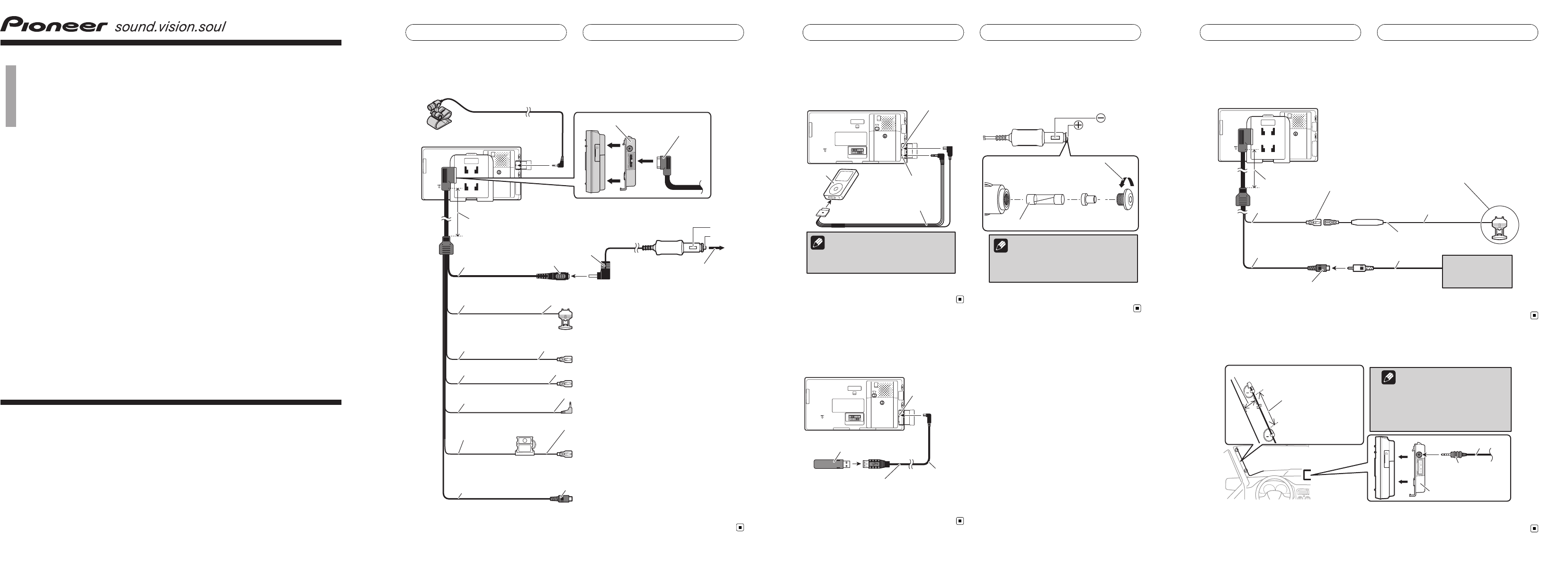
When connecting a rear view camera
20 cm (7-7/8 in.)
20 cm (7-7/8 in.)
2 m (6 ft. 7 in.)
5 m (16 ft. 5 in.)
7. Rear view camera
(e.g. ND-BC2)
(sold separately)
1. This product
5. Rear view camera input (Brown)
4. Extension lead (for reverse signal)
3. Fuse resistor
6. RCA cable (sold separately)
2. REVERSE-GEAR SIGNAL INPUT (Violet/white)
(Refer to Connecting the reverse signal and
parking brake leads.)
Fig. 5 Abb. 5 Afb. 5 Рис.5
Wiring the external antenna
35 cm — 75 cm
(1 ft. 2 in. — 2 ft. 6 in.)
2. Not over 10 cm (3–7/8 in.)
1.5 m (4 ft. 11 in.)
3. External antenna
4. Cradle
This wiring is unnecessary for
the Russian model.
The antenna is supplied with
ND-TMC3 (sold separately) for
the Australian model.
Notes
1.
Fig. 6 Abb. 6 Afb. 6 Рис.6
En
<F500BT_CONNECTION> -Page 1