


PicoScope 4000 Series Automotive Oscilloscope User's Manual2
© Copyright 2008 Pico Technology Ltd. All rights reserved.ps4000a.en
1.3
Installation instructions
Important
You must install the PicoScope software before connecting
a PicoScope 4000 Series Automotive Oscilloscope to your PC for the first
time.
Install the software by following the steps in the quick start guide supplied with your
oscilloscope. You can then connect your oscilloscope to the PC. To minimise the
risk of electromagnetic interference, please use the USB cable supplied.
There is no need for an additional power supply, as the unit draws its power from the
USB port.
Checking the installation
Once the software has been installed, ensure that the oscilloscope is connected to the
PC and then start the PicoScope software. The software should now display the
voltage of any signal that is connected to the oscilloscope. If you plug in a test lead
into the scope and touch the red clip or probe with your finger, you should see a small
signal (caused by mains pickup or other electrical noise) in the oscilloscope window.
Standard oscilloscope connectors
The PicoScope 4000 Series Automotive Oscilloscopes have standard oscilloscope
connectors. The input impedance is also standard, so add-on sensors and probes will
work correctly.
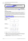
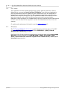
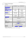
Connector diagrams
Rear view,
all models
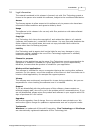
Front view,
PicoScope 4223
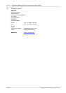
Front view,
PicoScope 4423
A. Ch A. Input channel A. Similarly for channels B, C and D.
E. LED. Lights up when the PicoScope 4000 Series Automotive Oscilloscope is first
powered up, switches off when the PicoScope software begins to run, and then
lights up again when the oscilloscope is sampling data.
F. USB port connector. Compatible with USB 1.1 and USB 2.0 ports.
9
9
10
9