


Contents: (1) Switch (2) Butt Connectors (2) Zip ties
(2) T-taps (1) Eyelet Connector (2) Blue, (1) Pink Connector
Installation:
1) Use supplied pink connector, crimp to RED wire on ReSpeed; crimp supplied eyelet to BLACK
wire.
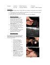
2) Use the supplied T-tap and tap RED wire into KEY ON +12 V usually located under the dash.
3) Connect the black wire to good clean ground.
4) Put the other T-tap on black wire to add speed limiter switch later (Figure 1).
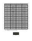
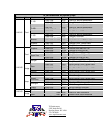
Speed Sensor Hook-up
5) The speed signal wires are usually
twisted together and sometimes
wrapped in black tape unless coming
from the ABS or PCM. One of these
wires is sensor ground and the other
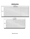
carries the signal. Refer to Chart D to
locate you speed signal wire. Cut the
speed signal wire.
6) Using supplied blue butt connectors,
connect the Respeeds Green wire to the
cut wire coming from sensor. The
green wire is the Respeed input and the
white wire is the output.
7) Connect the Respeeds white wire to the
wire going to PCM also using the
supplied blue butt connectors.
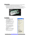
Speed Limiter Switch
The speed limiter switch turns the speed limiter
on the vehicle on or off. Pushing the switch
allows the ReSpeed module to see ground and
disable the speed limiter.
a. Mount the switch in an
accessible area(Figure 2).
b. Connect purple wire from
Respeed to one side of the
switch. The two blue
connectors will be connected
to each side of switch.
c. Connect supplied wire to the
other side of switch. Connect
the other side of supplied wire
to ground using pink connector
(Figure 3).
d. This can be done by crimping
pink connector to the supplied
wire (Figure 3), then
connecting that to the red T-tap
applied to ground wire earlier
in instructions. (Figure 4).
Figure 1
Figure 2
Figure 3
Figure 4