


REVISION A — 12/93 1
INSTALLATION MANUAL
BKMT10, BKMT10/230, AND BKMT10/24
BLOWER KITS
1.0 SCOPE
The information contained within this manual pertains
to the BKMT10, BKMT10/230, and BKMT10/24
blower kits.
Installation should be in accordance with all applicable
local and national electric codes, utilizing approved
materials only.
2.0 DESCRIPTION
The BKMT10, BKMT10/230, and BKMT10/24 are
continuous duty blower kits designed for use in either
the HT10V or MT10P liquid cooled enclosures.
2.1 MODELS
BKMT10 Blower kit, 6.7 watts @ 120 VAC,
60 Hz, 33 cfm
BKMT10/230 Blower kit, 8.9 watts @ 230 VAC,
50 Hz, 27 cfm
BKMT10/24 Blower kit, 1.92 watts @ 24 VDC
(AC rectified), 30 cfm
®
C468M
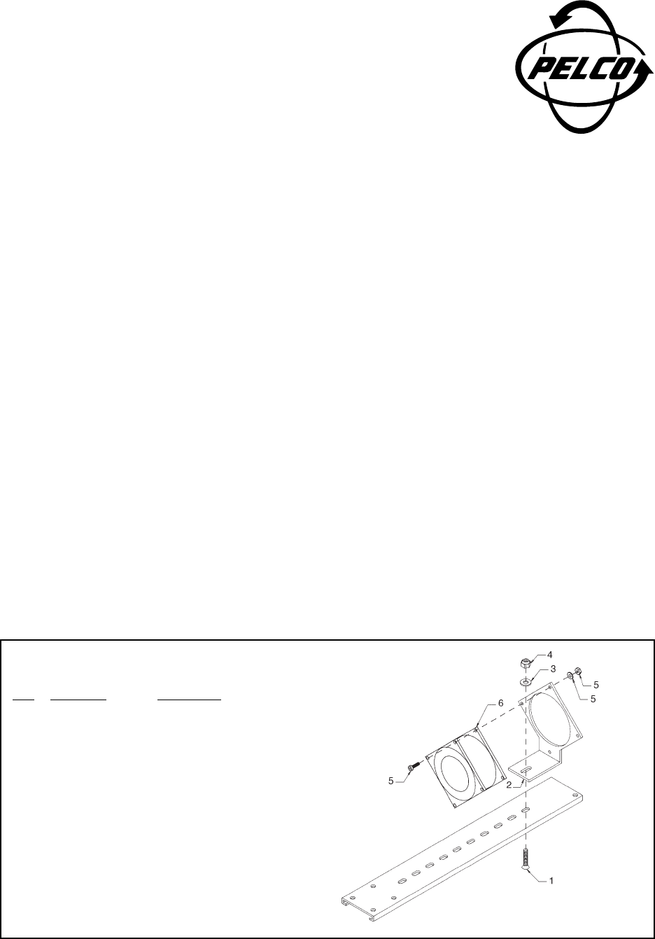
Figure 1. BKMT10 Series Blower Kit Installation
3.0 INSTALLATION
Install the blower kit in either the HT10V or MT10P
enclosure as outlined below.
1. Remove the rear plate of the enclosure, and
then remove the camera sled.
2. Assemble blower/blower bracket to sled as
shown in Figure 1, items 1–4.
3. Install sled into enclosure.
4. Wire blower to power source using butt
splices provided.
5. Re-install rear plate of the enclosure.
Item Description Part Number
1 1/4-20 bolt ZH1/420X.750SFS
2 Fan bracket BK40004001COMP
3 Washer ZH260X562X65C
4 Nut ZH1/420NUTCHN
5 Fan Securement
Assembly
Screw ZH4-40X.500SPP (Qty. 4)
Washer ZH4LWSIS (Qty. 4)
Nut ZH4-40NUTSH (Qty. 4)
6 Fans
24 VDC EH4600105W3
120 VAC EH4600115W3
230 VAC EH4600123W3