


5
43
off
on
2
off
on
1
6
ANTI-RESONANCE
DISABLE
AUTOMATIC STANDBY
Full Current
50% Current Standby
Anti-res. Enabled
Anti-res. Disabled
NO FUNCTION
NO FUNCTION
NO FUNCTION
NO FUNCTION
on
12
off off off
7
698
7698
10 11
CURRENT
S&D/CW&CCW
2
0.14
0.26
0.39
0.51
0.64
0.76
0.89
1.01
1.14
ES21BS 1.26
1.38
ES22BS 1.51
1.63
ES23BS 1.76
1.88
2.01
2.14
ES31BS 2.26
ES21BP 2.38
2.51
2.63
2.76
ES32BS 2.88
3.01
ES22BP 3.13
3.26
3.38
ES33BS 3.50
3.63
3.75
3.88
ES31BP, ES32BP, ES33BP
4.00
off off
off off onoff off
off on offoff off
off on onoff off
off off offoff on
off off onoff on
off on offoff on
off on onoff on
off off offon off
off off onon off
off on offon off
off on onon off
off off offon on
off off onon on
off on offon on
off on onon on
on off offoff off
on off onoff off
on on offoff off
on on onoff off
on off offoff on
on off onoff on
on on offoff on
on on onoff on
on off offon off
on off onon off
on on offon off
on on onon off
on off offon on
on off on
on on
on on offon on
on on onon on
45123
off off
123456789101112
SW 1112
(amps)
Step & Direction Indexer
Clockwise & Counterclockwise Indexer
off
on
off
on
off
off
on
on
WAVEFORM
2
10 11
onon
AUTOMATIC TEST
2
-4% 3rd harmonic
-
10% 3rd harmonic
-6% 3rd harmonic
Pure sine
Default Setting
off
on
on
off
off
off
on
on
off
off
on
on
off
off
on
on
off
off
off
on
on
off
on
on
off
off
off
off
on
on
on
on
off
off
off
off
off
off
off
off
on
on
on
on
on
on
on
on
on
ononon on
off
on
off
on
off
off
on
off
on
off
on
off
on
off
on
50,800 steps
50,000 steps
36,000 steps
25,600 steps
25,400 steps
25,000 steps
21,600 steps
20,000 steps
18,000 steps
12,800 steps
10,000 steps
5,000 steps
2,000 steps
1,000 steps
400 steps
200 steps
Default Setting
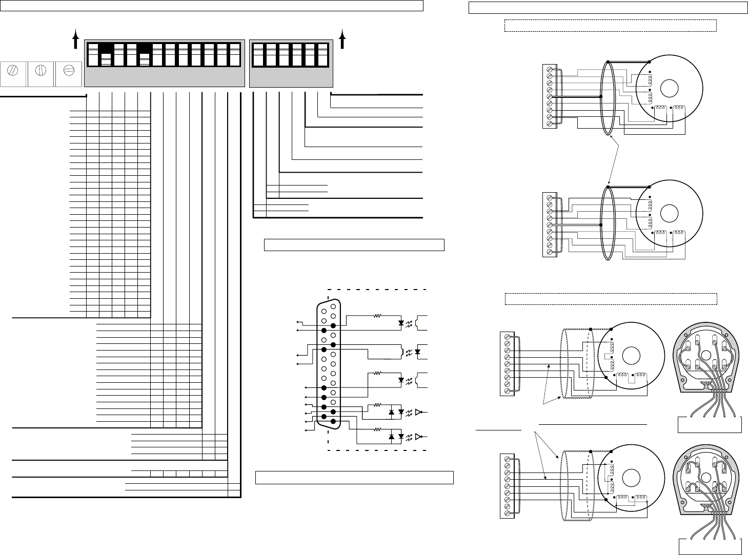
2. The drive reads these switches only upon power up. It reads all other switches continuously.
D I P S W I T C H S E T T I N G S
2
RESOLUTION
(steps per revolution)
Phase
Balance
Phase A
Offset
Phase B
Offset
Motor matching
Access through the top of the chassis (loosen screws, move cover plate)
off
123456
SW 216
Series Connection
Red
Blue
Yellow
Black
White
Brown
Orange
Green
Parallel Connection
Shield is connected to the motor case and
is internally connected to the ground pin
on the drive’s AC power connector.
PM
Phase A
Windings
Phase B
Windings
Motor
Yellow
Blue
Red
Black
Shield
White
Green
Orange
Brown
PM
Phase A
Windings
Phase B
Windings
Motor
Shield
INTERLOCK
A
CENTERTAP
A+
A–
EARTH
B+
B–
B
CENTERTAP
INTERLOCK
INTERLOCK
A
CENTERTAP
A+
A–
EARTH
B+
B–
B
CENTERTAP
INTERLOCK
ES AND OS MOTORS
End Cover RemovedSchematic View
PM
Phase A
Windings
Phase B
Windings
1
6
5
3
28 74
Wire #1
Wire #3
Gnd (Grn/Ylw)
Wire #2
Wire #4
INTERLOCK
A
CENTERTAP
A+
A–
EARTH
B+
B–
B
CENTERTAP
INTERLOCK
1
2
7
8
4
6
5
3
Gnd 1 3 2 4
EARTH A+ A- B+ B-
PM
Phase A
Windings
Phase B
Windings
1
6
5
3
28
74
Wire #1
Wire #3
Gnd (Grn/Ylw)
Wire #2
Wire #4
INTERLOCK
A
CENTERTAP
A+
A–
EARTH
B+
B–
B
CENTERTAP
INTERLOCK
1
2
7
8
4
6
5
3
Gnd 1 3 2 4
EARTH A+ A- B+ B-
Series Connection
Parallel
Connection
RS AND TS MOTORS
M O T O R C O N N E C T I O N S
DO NOT LENGTHEN OR REMOVE INTERLOCK JUMPER
DO NOT LENGTHEN OR REMOVE INTERLOCK JUMPER
The green/yellow (Gnd) wire is for safety purposes. The shield connection
to the motor case is for EMI purposes (the C10 cable kit provides hardware
for the shield connection). C10 cable assembly instructions are provided
in the C10 cable kit.
13
12
11
10
9
8
7
6
5
4
3
2
1
25
24
23
22
21
20
19
18
17
16
15
14
Shutdown–
Shutdown+
Direction–
Direction+
Step–
Step+
Reset+
Reset–
Fault C
Fault E
Internal Connections
INPUTS & OUTPUTS
Controller
Connections
AC Input
........ 95-132VAC, 50/60Hz, single phase
POWER
STEP
OVER TEMP
MOTOR FAULT
Green when power is on
Green when drive receives step
Flashes Red/Green in auto test
Red indicates over temp fault
Red when drive detects short
circuit in motor or motor cable;
Red if interlock is open
STATUS LEDS