


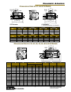


Determination of Valve Torque
By properly sizing an actuator to a valve for a specific
application, performance is guaranteed and economies are
gained. Before an actuator can be sized for an application,
the amount of torque required must be determined. The
operating torque of a ball valve is influenced by the design,
seat material, and application (service) conditions.
Stem torque is primarily dependent upon the tightness of the
stem nut. The design of the SB Series Ball Valve is such
that the stem torque is constant. Ball/seat torque is created
by the friction between the ball and seat and is also very
sensitive to service conditions. The “floating ball” design
concept allows the system pressure to force the ball into the
downstream seat. The higher the system pressure, the
harder the ball is forced into the downstream seat, and,
therefore, the higher the torque. Also, since different seat
materials have different coefficients of friction, the ball/seat
torque also becomes a function of the seat material being
used.
Valve torque is also a function of the media flowing through
the valve. Abrasive medias have a tendency to increase the
amount of friction between the ball and seats, whereas some
light oils, which provide additional lubricity, may reduce the
amount of torque required.
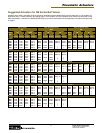
The pressure torque curves on page 7 are the result of
laboratory testing using water at ambient temperature as the
medium. Torque values derived from these curves, when
the appropriate service condition correction factors are
applied, will be adequate for the vast majority of applications.
Based upon the valve size, seat material, and differential
pressure across the valve (in the closed position), the
amount of torque required may be determined using the
following procedure:
1. Find the valve torque from the appropriate curve by
using the differential pressure. Locate the differential
pressure on the horizontal axis of the chart and move up
until you arrive at the appropriate valve size. Transfer
the intersecting point across to the vertical axis of the
graph and read the required torque.
2. Multiply this torque by the service and media application
factor multipliers. The maximum combined multiplier
should never be greater than 2.
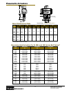
When the torque requirements have been determined,
the actuator may be properly sized.
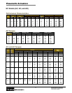
1. Double Acting Operation (AD)
Select the actuator whose torque output, at the
minimum air supply pressure, exceeds the calcu-
lated torque. Actuator torque output charts are
shown on pages 8 and 9.
2. Spring Return Operation, Fail Closed (AC)
Select the actuator whose spring torque output
exceeds the calculated torque. Actuator torque
output charts are shown on pages 8 and 9. In
addition, check the selected actuator to insure the
air torque output at the minimum air supply pressure
also exceeds the calculated torque.
3. Spring Return Operation, Fail Open (AO)
Select the actuator whose spring torque output
exceeds the calculated torque. Actuator torque
output charts are shown on pages 8 and 9. In
addition, check the selected actuator to insure the
air torque output at the minimum air supply pressure
also exceeds the calculated torque.
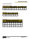
A. Service
On-Off 1.00
Emergency shutdown (cycled
less than once per month) 2.00
Applications with less than two
cycles per day 1.20
Applications below –20 ˚F (-29 ˚C) 1.25
B. Media
Saturated steam 1.20
Clean saturated steam 1.00
Liquid, clean (particle free) 1.00
Liquid, dirty (slurry), raw water 1.80
Gas, clean and wet 1.20
Gas, clean and dry (superheated stm.) 1.00
Gas, dirty (natural gas) 1.50
Chlorine 1.50
Application Factor Multiplier
Actuator Selection
Parker Hannifin Corporation
Instrumentation Valve Division
Jacksonville, Alabama
Pneumatic Actuators
6