


SET-UP RAIN GAUGE
Questions or comments? Contact our Customer Service Center
website: www2.oregonscientific.com/service phone: 800.853.8883 email: helpme@oscientific.com
D
SET-UP POLE
E
*To test the rain gauge you need to move the arrow to the bar graph section
by rotating the dial.
Press the SELECT button on the black rotating dial until the selected area
icon ( ) is on the BAR GRAPH on the LCD.
Press the MODE button on the black rotating dial until the selected area icon
is switched to Rainfall.
Tilt the tipping funnel on the rain gauge several times and verify a numerical
reading on the base unit ( ).
6
7
8
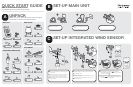
Secure the battery cover with eight screws.
After verifying connection to the base station, place the rain gauge on a level
surface and place a few drops of water on the cross at the base of the funnel
to check the horizontal level. You can adjust the level when securing the rain
gauge on the level screws by using the mounting screws.
To complete the installation, slide the hood cover on and secure with two
base screws located on the bottom rim of the rain gauge.
9
10
11
Remove the two base screws located on the bottom rim of the rain gauge
and slide the hood cover off to expose the battery compartment.
Locate the battery compartment and remove the eight screws that secure the
cover. Install two AA batteries.
Remove the packing tape from the tipping funnel.
1
2
3
Press the RESET button.
Before proceeding to install the rain gauge outside, please verify
communication to the main base station.
Press the SEARCH button to initiate a wireless sensor search.
5
4
6
1 3
2
7
8 9
11
10
4
5
7
8
9
1
2 3
5
4
6
Screw off the included nut and bolt from the plastic base.
Remove the round pole cover in the middle of the plastic base.
Insert the bottom pole until the screw hole aligns with the plastic base.
Re-insert the nut and bolt and fasten. Screw the “cone shape” end clockwise
onto the bottom pole.
Use the guiding end to start inserting bottom pole at a perpendicular angle
into the ground.
Place a wooden block on the top of the bottom pole. With a hammer, hit the
wooden block to hammer the guiding end into the ground until the plastic
base reaches the base of the ground.
Attach the bottom pole with the middle pole, top pole, and the wind sensor
using three type A screws to secure.
Insert two rectangular base legs into the plastic base to firmly fix the pole to
the ground.
For better stability, drive the three pins into the ground and attach the tension
strings from the pins to the plastic hooks located on the top pole.
Rotate the North Indicator reference line to the North and align the wind
indicator in the same direction.
Press reset button on main unit to erase all testing data.
Option 1—With mounting pole
1
2
3
4
5
6
7
8
9
10
11
12
13 14
Detach the plastic connector at the end of the top pole by removing the type
A screw.
Using the two U-bolts, secure the plastic base on the existing pole using the
four washer and bolts.
Insert the top pole into the plastic base while aligning the holes to re-insert the
bolt and secure by screwing the nut.
Assemble the wind sensor main body horizontally to the top pole and secure
with a type A screw.
Rotate the North Indicator reference line to the North and align the wind
indicator in the same direction.
Press reset button on main unit to erase all testing data.
Option 2—With side mounting kit on an existing pole
10
11
12
13
14