


EN
4
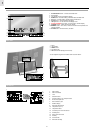
VFD DISPLAY
ACTIVATE / DEACTIVATE THE DISPLAY
Slide the VFD control switch at the back of the weather station to different display
options:
• Display ON – The VFD display and the LED light bars will always be on.
• Display OFF – The VFD display and the LED light bars will always be off.
• Display AUTO – The VFD display and the LED light bars will be on when any
key is pressed or the front of the ACTIVE / SNOOZE touch panel is triggered.
The display and the light bars will be turned off after 30 minutes if no other
keys are pressed.
REMOTE SENSOR
This product is shipped with the RTGR328N Thermo / Hygro Sensor. The main
unit can collect data from up to 5 sensors (5 Thermo / Hygro Sensors). The
THGR328N and THGR228N sensors are also compatible with this weather
station. (Additional sensors are sold separately. Contact your local stockist for
more information).
The RTGR328N Sensor collects temperature and humidity readings, and signals
from official time-keeping organizations for the radio-controlled clock.
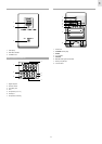
SET UP THERMO / HYGRO SENSOR (RTGR328N)
1. Open the battery compartment with a small Phillips screwdriver.
2. Insert batteries.
3. Set the channel and radio signal format. The switches are located in the
battery compartment.
4. Press RESET, then set the temperature unit.
5. Close the battery compartment.
To fold out the stand:
For best results:
• Insert the batteries and select the unit, channel, and radio signal format
before you mount the sensor.
• Place the sensor out of direct sunlight and moisture.
• Do not place the sensor more than 30 metres (100 feet) from the main
(indoor) unit.
• Position the sensor so that it faces the main (indoor) unit, minimizing
obstructions such as doors, walls, and furniture.
• Place the sensor in a location with a clear view to the sky, away from metallic
or electronic objects.
• Position the sensor close to the main unit during cold winter months as
below-freezing temperatures may affect battery performance and signal
transmission.
NOTE The transmission range may vary and is subject to the receiving range of
the main unit.
SWITCH OPTION
Channel If you are using more than one sensor, select a
different channel for each sensor.
Radio Signal Format EU (DCF) / UK (MSF)
SWITCH OPTION
Temp °C / °F
1
2
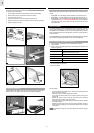
GETTING STARTED
INSTALLING THE WALL-MOUNT HOLDER
To install the wall-mount holder:
1. Use the diagram provided to mark where the 6 screws will be drilled.
2. Drill the screws into the wall to affix the wall-mount holder.
3. Put on the wall-mount cover.
4. Unscrew the bar that is in the Mirror Weather Station stand.
5. Attach the stand to the wall-mount holder and screw to affix firmly in place.
6. Adjust the angle of the mirror.
AC ADAPTOR (MAIN UNIT)
Please install the AC adaptor at the back of the unit as illustrated. (Hiding of the
adaptor wire can only happen when the wall-mount holder is installed).
1 2
3 4
5 6