


300-302 Series Page 13 of 31
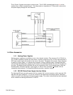
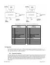
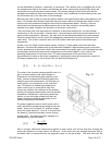
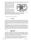
On the controller card there is a jumper that sets whether the control loop controls mass flow or an
external process variable. See Figure 2.7. If the jumper is over the top two pins, the loop controls
mass flow. If the jumper is over the bottom two pins, the loop controls an external process variable.
This process variable signal must be supplied on pin 12 of the D connector (for U pin out units) of the
measurement card. When the controller is set for external variable control it will open or close the
valve as necessary to make the external process variable signal match the command signal. The
command signal may be 0-5 volts, 0-10 volts (4-20 ma for 4-20 ma input/output cards) or any value in
between. If the process variable has a response time that is much faster or slower than the flow
meter signal it may be necessary to adjust the gain potentiometer.
2.9. Command Input
The flow controller will operate normally with any command input signal between 0-5 volts (4-20 ma
for units with 4-20 ma input/output cards) If the command signal exceeds ±14 volts it may damage the
circuit cards. During normal operation the control loop will open or close the valve to bring the output
of the flow meter signal to within ± 0.001 volts of the command signal. The command signal will not
match the flow signal if there is insufficient gas pressure to generate the desired flow. If the
command signal exceeds 5 volts the controller will continue to increase the flow until the output
matches the command signal. However, the flow output does not have any guaranteed accuracy
values under these conditions.
If the command signal is less than 2% of full scale (0.1 volts or 4.32 ma) the valve override control
circuit will activate in the closed position. This will force the valve completely closed regardless of
the flow signal.
2.10. Valve-Override Control
The valve override control line provides a method to override the loop controller and open or close the
valve regardless of the flow or command signals. During normal operation this line must be allowed to
float freely. This will allow the loop control to open and close the valve as it requires. If the valve
override line is forced high (> +5 volts) the valve will be forced full open. If the valve-override line is
forced negative (< -5 volts) the valve will be forced closed.
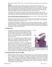
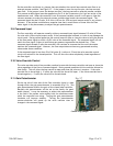
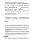
2.11. Gain Potentiometer
On the top left of inlet side of the flow controller there is a hole
through which the gain potentiometer is accessible (Fig 2.3). This
gain potentiometer affects the gain of the closed loop controller.
Normally this potentiometer will be set at the factory for good
stable control. It may be necessary to adjust this potentiometer
in the field if the system varies widely from the conditions under
which the controller was setup. Turning this gain potentiometer
clockwise will improve stability. Turning the potentiometer
counter-clockwise will speed up the valve reaction time to
changes in the command signal.
Fig. 2.7
Gain Potentiometer
Control Loop Jumper