


and (-) to anode (the RC snubber is an
optional enhancement).
inductive loads, place a diode across
the load (PRV > DC supply, 1N4006
recommended) with (+) to cathode
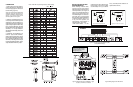
RELAY PROTECTION AND
EMI SUPPRESSION
When switching inductive loads,
maximum relay life and transient
EMI suppression is achieved using
external protection (see Figures 2
and 3). Place all protection devices
directly across the load and mini-
mize all lead lengths. For AC induc-
tive loads, place a properly-rated
MOV across the load in parallel with
a series RC snubber. Use a 0.01 to
0.1µF pulse film capacitor (foil
polypropylene recommended) of
sufficient voltage, and a 47Ω,
1/2W carbon resistor. For DC
Load
Diode
(optional)
Power
0.1uF
Film
Figure 2: DC Inductive Loads
47 ohm
1/2W
Relay
Contacts
+
-
Load
Power
MOV
0.1uF
Film
Figure 3: AC Inductive Loads
47 ohm
1/2W
Relay
Contacts
Figure 4: Input Range/Function Selection (SW1)
Factory Default Settings
WARNING: Do not attempt to
change any switch settings
with power applied. Severe
damage may occur!
Figure 5: DRG-AR-TC Factory Calibration: J-Type,
0 to 350°C, A-HI/B-LO, non-failsafe
CALIBRATION
1. After configuring the DIP switches,
connect the input to a calibrated TC
source and apply power. Refer to the
terminal wiring (Figure 5).
NOTE: to maximize thermal stability, final
calibration should be performed in the
operation installation, allowing approxi-
mately 1 to 2 hours for warm up and
thermal equilibrium of the system
.
2. Setpoint: set deadband at its mini-
mum (fully counter clockwise) before
adjusting the setpoint. With the de-
sired trip thermocouple millivolt input
applied, adjust setpoint until the relay
trips. For HI trip calibration, start with
the setpoint above the desired trip (full
clockwise). For LO trip calibration,
start below the desired trip (full counter
clockwise).
3. Deadband: Set deadband to its
minimum (fully counter clockwise).
Set the setpoint to desired trip. Adjust
thermocouple millivolt input until relay
trips. Readjust deadband to 5% (fully
clockwise). Set voltage/current input
to desired deadband position. Slowly
adjust deadband until relay untrips
Table 1: DRG-AR-TC Input Range Selector -Switch Settings
KEY: = ON
DIMENSIONS
Figure 6: Wiring Diagram for DRG-AR-TC