


stop
before retainer screws are replaced.
**
When installing float/guide assembly make certain that the end of the guide fully engages the inlet
float
*
Do
not use cleaning agents
that will damage float, tube or O-rings.
float stop retainer holes.
Reinsert the retainer screws and tighten. Disengage the extractor tool.
step on the outlet float stop assembly. Change the Teflon tape on the plugs and reinstall.
Repeat this last
flwt
and inlet stop are reinserted in the meter rotate the extractor tool to line up the float stop dimples and
the threaded
float
and stop assembly make certain the float is not damaged by the threads on
the side port
Use caution as the float enters the tube.
glass tube.
The tube will be easily damaged if a cocked float is forced against the
When the
Roat
stop from the fitting cavity. Use care. The float will follow the
stop out of the cavity. Then remove the top float stop in the same fashion. The tube is now ready for in place cleaning (as indi-
cated above).
of the fitting.
When refitting the
Thread
the extractor tool onto the float stop assembly.
Remove the inlet float stop retoiner screws and gently pull the
extrac-
2.
If the tube is ribbed (i.e. fluted or beaded),
remove the
bottom plug.
threaded
holes, insert and thread the float stop retainers into the fitting. Tighten them down.
tor tool. Remove and replace the Teflon tape on the plugs. Replace plugs in end fittings.
Disengage the
Line
up the dimples on the
float stop with
carefull
y guide the float assembly back into the tube. ”
muy be cleaned with the same fluid. (This unit is not
meant to be disassembled.) To reassemble,
a
bottle brush and an appropriate mild soap solution*. (It is normally not necessary to remove the inlet float
stops when tubes have pole-guided floats.) The guide and float assembly
taper
(has a pole-guided float) thread the extractor tool onto the threaded guide extension in the outlet fitting.
Remove the float stop retainers, and carefully withdraw the float and guide assembly from the tube. The tube is now fully accessi-
ble for cleaning with
plain
for
throttling purpos-
es. Depending on the installation, valves may not be essential, but they are most useful in many installations. Remember to get a
correct reading of flow in gas service. It is important to know the pressure right at the outlet of the meter (before the valve).
1.
If the tube is
l/2
pipe diometers from the meter ports. The valve at the outlet should be used to create back pressure as
required to prevent floot bounce. It should be set initially and then left alone. The inlet valve should be used
-
Several
feet of pipe as long as significant vibration or stress resulting from
misaligned pipe are not factors.
Flowmeters with plastic fittings must be installed so that fittings are not made to support any part of the associated plumbing.
Clamps mounted to a bulkhead or panel can be used to hold the meter securely at both ends.
Flowmeters used in gas service should have suitable valves plumbed in at the inlet and outlet of the meter. These valves should be
no more than 1
Flowmeters
with stainless steel fittings will support
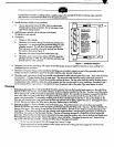
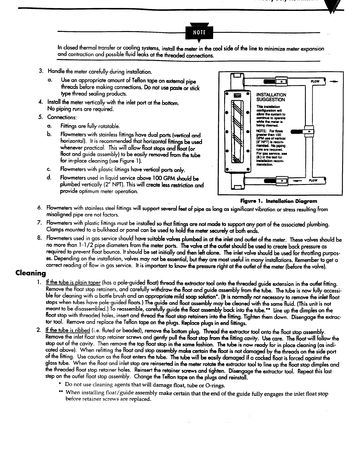
Figurm
1. Installation Diagram
m
0
?
?
?
e
NPT).
Th
is will create less restriction and
provide optimum meter operation.
Flowmeters
used in liquid service above 100 GPM should be
plumbed vertically (2 ”
Roar and guide assembly) to be easily removed from the tube
for in-place cleaning (see Figure 1).
Flowmeters with plastic fittings have vertical ports only.
the
inlet port at the bottom.
No piping runs are required.
Connections:
a.
b.
C.
d.
Fittings are fully rotatable.
Flowmeters with stainless fittings hove dual ports (vertical and
horizontal). It is recommended that horizontal fittings be used
whenever practical. This will allow float stops and float (or
pipe
threads before making connections. Do not use paste or stick
type thread sealing products.
Install the meter vertically with
install the meter in the cool
side of the
line to minimize meter
expansion
and contraction and possible fluid leaks at the threaded connections.
3.
4.
5.
6.
7.
8.
Cleaning
Handle the meter carefully during installation.
a.
Use an appropriate amount of Teflon tape on external
In closed thermal transfer or cooling systems,