


2
PREPARATION
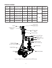
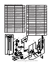
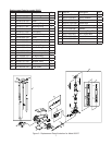
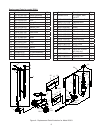
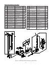
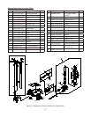
Assembly (see Replacement Parts pages 6~9 for reference to parts location & assembly sequence)
Assemble, align and insert the handle assembly & handle position bar into the handle sleeve, then tighten the bolt
on handle sleeve to prevent accidental removal of handle while in use.
Before Use
1.
Verify that the product and application are compatible, if in doubt call Omega Technical Service (888) 332-6419.
2. Before using this product, read the operator's manual completely and familiarize yourself thoroughly with the
product, its components and recognize the hazards associated with its use.
3. To familiarize yourself with basic operation, locate and turn the release valve (handle knob):
a. Clockwise until rm resistance is felt to further turning. This is the ‘CLOSED’ release valve position used to
raise the load.
b. Counter-clockwise, but no more than 1 full turn from the closed position. This is the ‘OPEN’ release valve
position used to lower the load. The more you turn the release valve counter-clockwise, the faster the load
descends.
4. With ram fully lowered, remove the oil ller screw. Check oil level. Proper oil level should be just below the rim of
the opening. Reinstall the oil ller screw.
5. Pour a teaspoon of good quality air tool lubricant into the air supply inlet of the lift control valve. Connect to air
supply, then squeeze the lift control valve for 3 seconds to evenly distribute lubricant.
Note: These models are equipped with the popular 1/4" NPT air coupler. When installing a different air coupler of
your choice, ensure that thread tape or compound is used when servicing connections. To ensure dependable,
trouble free operation an inline air dryer and oiler is recommended.
6. Ensure that jack rolls freely. Raise and lower the unloaded ram throughout the lifting range before putting into
service to ensure the jack operates smoothly. Replace worn or damaged parts and assemblies with Omega
authorized replacement parts only.
Bleeding / Venting Trapped Air
With the release valve in the OPEN position (3b.) and with ram fully lowered, locate and remove the oil ller screw.
This will help release any pressurized air which may be trapped within the reservoir. Reinstall the oil ller screw.
SAFETY and GENERAL INFORMATION
Save these instructions. For your safety, read, understand, and follow the information provided with and on this jack
before using. The owner and operator of this equipment shall have an understanding of this jack and safe operating
procedures before attempting to use. The owner and operator shall be aware that use and repair of this product
may require special skills and knowledge. Instructions and safety information shall be conveyed in the operator's
native language before use of this jack is authorized. If any doubt exists as to the safe and proper use of this jack,
remove from service immediately.
Inspect before each use. Do not use if broken, bent, cracked or damaged parts are noted. Any jack that appears
damaged in any way, or operates abnormally shall be removed from service immediately. If the jack has been or
suspected to have been subjected to a shock load (a load dropped suddenly, unexpectedly upon it), immediately
discontinue use until jack has been checked by a factory authorized service center (contact distributor or manufacturer
for list of authorized service centers). It is recommended that an annual inspection be done by qualied personnel.
Labels and Operator's Manuals are available from manufacturer.
!
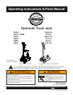
PRODUCT DESCRIPTION
These Hydraulic Truck Jacks are designed to lift, but not support, rated capacity partial vehicle loads consisting
of one end of a vehicle. Immediately after lifting, loads must be supported by a pair of appropriately rated jack
stands.
NEVER use a hydraulic truck jack as a stand-alone device. After lifting, immediately support
the lifted vehicle with a pair of appropriately rated jack stands.