SMART-AG™
This guide provides the basic
information you need to set up and begin
using your new SMART-AG, a combined
L1 GNSS receiver and antenna with
Emulated Radar (ER) output. For more
detailed information on the installation
and operation of your receiver, please
refer to the SMART-AG and OEMV user manuals, which can be
found on our website at
http://www.novatel.com/support/docupdates.htm
To order a printed copy of the manuals, free of charge, follow the
instructions given on the enclosed User Manuals postcard.
The SMART-AG supports Emulated Radar (ER) and Bluetooth®
functionality. Drivers and installation instructions, where
required, are available in the associated drivers directory of the
CD provided. An installation program for NovAtel’s PC Utilities,
including the CDU (Control and Display Unit) user interface, and
the OEMV Software Development Kit are also on the CD.
LEDs on the front of the SMART-AG provide receiver status
information. See the Status Indicators section of the SMART-AG
User Manual for further information.
SMART-AG CONTENTS
Accompanying this quick start guide, the following are also
provided with your SMART-AG:
• 1 CD containing:
• An installation program for NovAtel’s Control and
Display Unit (CDU) graphical user interface software
• Product documentation, including user manuals
• 1 User Manual postcard for requesting printed manuals
• Mounting Plate
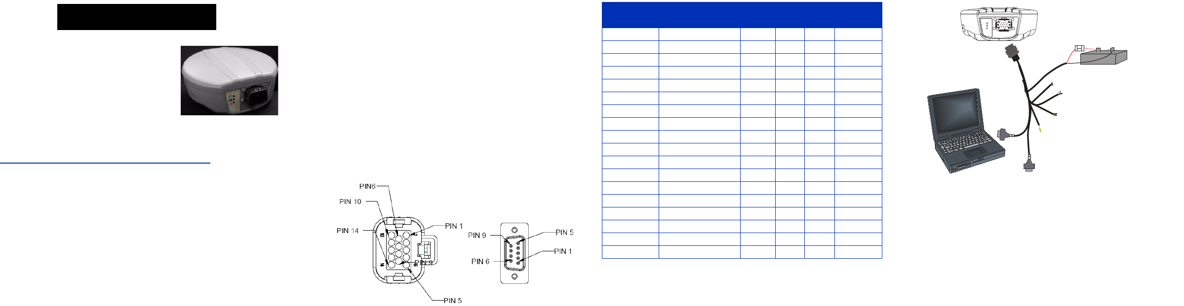
• 1 SMART-AG cable for power and communications:
The cable has two DB-9 connectors, see Figure 1. One
can accommodate a PC/laptop serial (RS-232)
communication port and the other can connect to a
modem or radio transmitter to receive differential
corrections (refer to your user-supplied modem or radio
transmitter information for its connectors).
At the other end is a 14-pin connector, see Figure 1. In
addition, there are a number of bare wires where the
outer insulation is cut away but the wires beneath are
intact. See Table 1 below for their pinouts. This cable is
RoHS compliant and its part number is 01018256.
The SMART-AG cable provides a means of supplying
power from a battery while operating in the field. The
bare wires (red for positive and black for negative) can
then be tied to a battery supply capable of at least 5 W.
Figure 1: 14-pin and DB-9 Pin Numbers
Table 1: SMART-AG Cable Wire Colors
ADDITIONAL EQUIPMENT REQUIRED
The additional equipment listed below is required for a basic
setup:
• A Windows-based PC with an RS-232 DB-9 port
• A battery connection (+8 to +36 V DC)
SETTING UP YOUR SMART-AG
Complete the steps below to connect and power your receiver.
1. Mount the SMART-AG on a secure, stable structure with an
unobstructed view of the sky.
2. Connect the SMART-AG to a DB-9 serial port on the PC.
3. Connect power to the SMART-AG. The cable’s red wire
(connector pin 14) is to be connected to the positive side of a
12 or 24V vehicular power circuit (or equivalent) protected
by a 5A fast blow fuse (user supplied). The cable’s black
wire (connector pin 9) is to be connected to the negative side
of the power circuit. If a SMART-AG cable (NovAtel part
number 01018256) is not used, a minimum wire size of
0.5 mm/ 20AWG must be used.
Wire Color Signal Name
14-pin
(J1)
DB-9
(J2)
DB-9
(J3)
Label
Red COM1_TXD 1 2
White COM1_RXD 2 3
Red COM2_TXD 3 2
White COM2_RXD 4 3
Black COM1 GND 5 5
Black COM2 GND 5 5
White-Black MMI GND 5 MMI GND
White-Black ER GND 5 ER GND
White-Black PPS GND 5 PPS GND
Yellow CANI+ 6 CANI+
Green CANI- 7 CANI-
- NO CONNECT 8
Black PWR RET (GND) 9 BATT-
Blue EMD RADAR OUT 10 ER_OUT
White MAN MARK IN 11 MMI
Orange PPS 12 PPS
- NO CONNECT 13
Red PWR INPUT 14 BATT+
+
-
Emulated Radar
MKI
PPS
CAN
COM
COM
User Supplied
5A Fast Blow
Fuse


