


128-6773
11 of 28
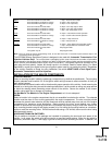
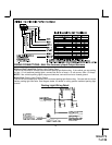
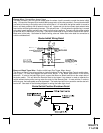
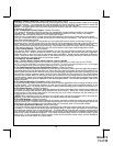
Orange Wire: Ground When Armed Output
This wire provides a 300 mA ground output when the alarm circuit is armed to control the starter inhibit
relay. Connect the Orange wire to terminal #86 (orange wire) of the relay provided. Connect terminal #85
(red wire) of the relay to an ignition wire in the vehicle that is +12 volts when the ignition switch is turned to
the on and start positions and off when the key is off. Locate and cut the low current start solenoid wire
found at the vehicles ignition switch harness. This wire will have + 12 volts when the ignition key is moved
to the start (crank) position and will have 0 volts in all other key positions. Connect one side of the cut wire
to terminal #87a ( Black wire) of the relay. Connect the other side of the cut wire to terminal #30 (White/
Black wire) of the relay. See below for detail of wiring, also see Yellow Start wire detail for connection to
vehicle considerations.
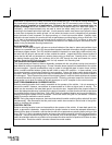
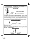
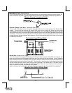
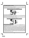
Brown w/ Black Trace Wire: Positive Inhibit Input Plus Trigger When Armed
The Brown w/ Black Trace wire provides an instant shutdown for the Remote Start Control module when-
ever it gets + 12 volts also triggers the alarm when armed. If the Brake lights switch in the vehicle
switches + 12 volts to the brake light circuit, connect the Brown w/ Black trace wire to the output side of
the brake switch. This will allow the Remote Start to shut down if an attempt is made to operate the
vehicle without the key while running under the control of the Remote Start. In most vehicles, in order to
shift into gear, the brake pedal must be depressed. The brake input will in turn cause the remote start unit
to shut off. See detail in the following diagram for wiring the brake light circuit.
Brake Switch Positive Shutdown Detail
Starter Inhibit Wiring Detail
BlackWhite/Black
10