


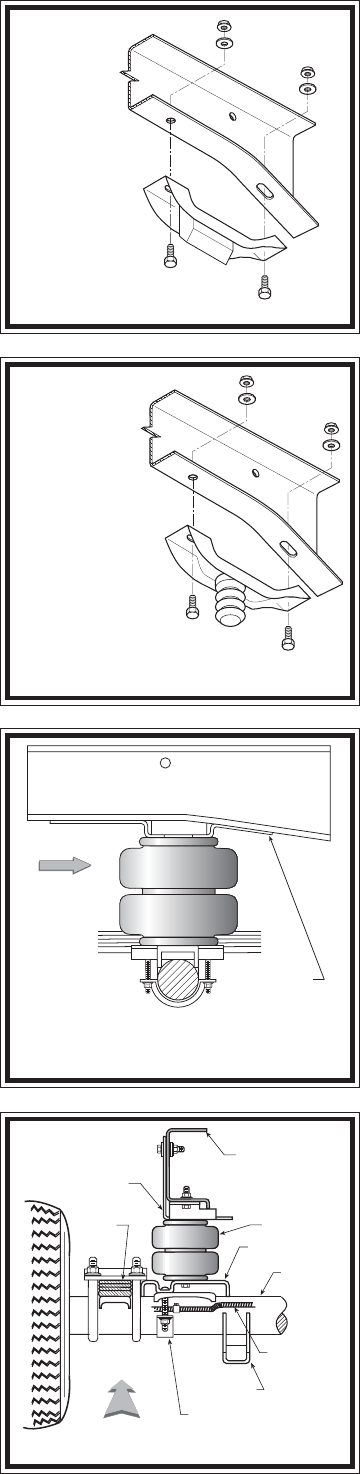
FIGURE "B"
FIGURE "C"
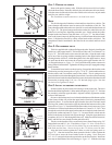
STEP 1 - PREPARE THE VEHICLE
Remove the positive battery cable. With the vehicle on a solid, level surface
chock the front wheels. Raise the vehicle by the axle and remove the rear wheels.
After the removal of the wheels lower the vehicle so the axle rests on jack stands
rated for your vehicles weight.
This installation assumes that there is no load in the truck.
NOTE:
This kit is designed to fit both two-wheel and four-wheel drive vehicles. The
jounce bumper and brackets must be removed for installation of this kit. The
jounce bumper and bracket on the two-wheel drive can be unbolted and removed
see Figure "B". The jounce bumper and bracket on the four-wheel drive may be
bolted or riveted in place, depending on model year. Simply unbolt the jounce
bumper bracket and remove from the frame see Figure "C". On older models,
remove the jounce bumper by drilling out two rivets that fasten the bracket to the
frame. Complete the removal by cutting off the heads with a cold chisel. The
completion of the kit installation is the same for the two-wheel and four-wheel
drive.
STEP 2 - PRE-ASSEMBLE THE KIT
This kit is supplied with a right and left upper bracket. Begin by installing the
left (driver's side) upper bracket. This bracket will have the "over-bent tab" see
Figure "D". The lower bracket is the same for both sides. Align the studs on the
top of one of the air springs with the mounting holes in the upper bracket while
ensuring that the air hole is visible through the slot in the upper bracket. Insert
the studs into the holes and secure the air spring to the upper bracket with 3/8"
-16 flanged lock nuts see Figure "A". Next, install the male push-to-connect air
fitting in the air inflation hole. Tighten the air fitting securely to engage the orange
thread sealant.
To attach the lower bracket to the air spring, first position the bracket on the
axle housing over the jounce pad see Figures "A" & "E". Position the bracket so
that the narrow end is toward the center of the vehicle. The air spring must be
secured to the lower bracket through the forward hole. Once the correct mounting
hole for the lower bracket has been identified, remove the bracket from the axle and
fasten to the air spring using a 3/8" -16 x 3/4" hex bolt (finger tight). Note that
this bolt will be tightened in Step 3.
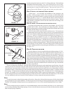
STEP 3 - INSTALL THE ASSEMBLY TO THE VEHICLE
Set the assembly in place on the axle housing over the jounce pad. The lower
bracket should butt against the U-bolts on the leaf spring see Figure "E". Position
the assembly so that the upper bracket is aligned vertically against the outside
surface of the frame rail.
On some vehicles there may be a rivet head on the bottom of the bottom surface
of the frame rail that will prevent the upper bracket from being mounted flush
against the frame. To assure that the upper bracket clears the rivet head, install
four large flat washers between the upper bracket and the bottom surface of the
frame rail see Figure "A". Installation of the flat washers is only necessary if your
vehicle has a rivet head on the bottom of the frame rail. Insert a 1/4" -20 x 1" bolt
through the vertical tab of the upper bracket and an existing hole in the frame rail.
Secure with washers and a nut see Figure "A". On some models, a hole must be
drilled in the frame rail for the bolt to pass through. Using the upper bracket as
a template, drill a 5/16" hole though the frame rail. Make sure that all electrical,
brake, and fuel lines are cleared from the path of the drill.
The tabs on the bracket will be secured to the lower frame flange using 3/8"
flanged lock nuts and 3/8"-16 x 1" hex bolts see Figure "A". Note: on the driver's
side of the vehicle the 1/4" bolt will also hold a clip (on some models) used to
hold brake and fuel lines. Secure the clip to the 1/4" bolt to secure the lines.
Align the lower bracket against the U-bolts over the leaf spring stack see
Figure "E". After the bracket has been squared with the U-bolts, tighten the
3/8" hex bolt to secure the lower bracket to the air spring. Next, insert two
3/8" -16 x 3" carriage bolts into the square holes on the lower bracket. Install one
axle strap on the bottom of the axle housing see Figure "A". Slide the axle strap
FIGURE "D"
FRONT
OVER-BENT
TAB
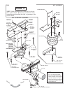
VIEW OF DRIVER’S SIDE ASSEMBLY
FROM INSIDE OF VEHICLE
DRIVER'S SIDE
FRONT
FRAME RAIL
AIR SPRING
LOWER BRACKET
UPPER BRACKET
BRAKE LINE
SHOCK
BRACKET
BRACKET STRAP
AXLE
LEAF
STACK
FIGURE "E"
TWO-WHEEL
DRIVE VEHICLES
SOME FOUR-WHEEL
DRIVE VEHICLES MAY
HAVE BOLTS, OTHERS
WILL HAVE RIVETS