


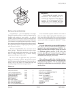
JOUNCE BUMPER
TO BE REMOVED
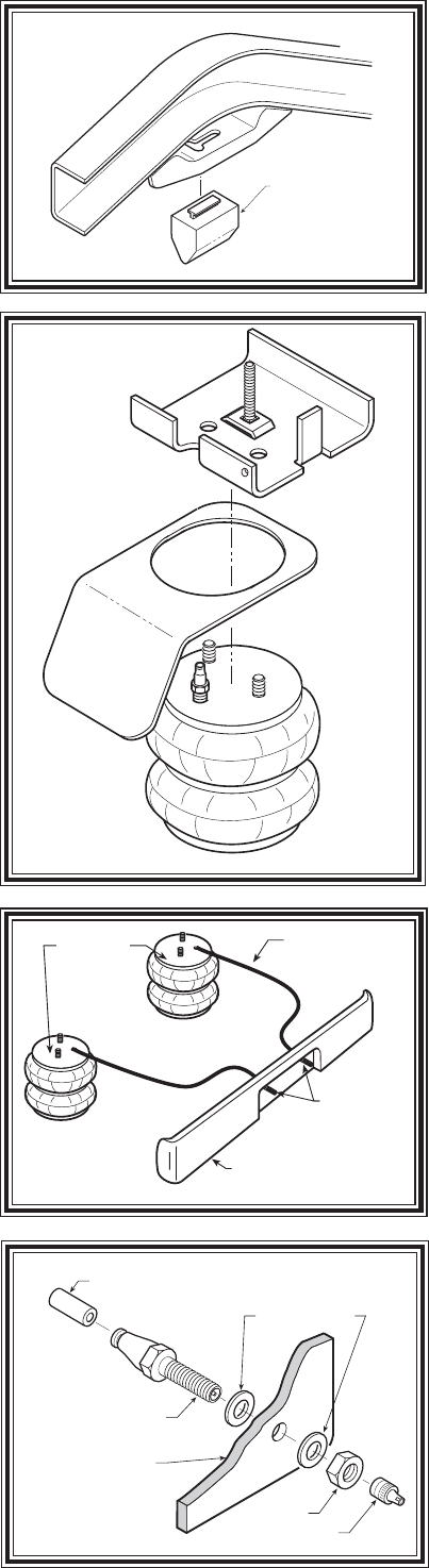
AIR HOSE
INFLATION
VALVES
BUMPER
AIR
SPRINGS
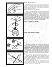
STEP 1 - PREPARE THE VEHICLE
Make sure that the vehicle is on a solid level surface. Take necessary
safety precautions such as using wheel chocks when working under your
vehicle. This vehicle does not have to be jacked up to install the kit.
Remove the positive battery cable. Remove the rubber jounce bumper
under the frame rail, see Figure "B".
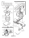
STEP 2 - PREASSEMBLE THE RIDE-RITE KIT
Select one air helper spring from your kit and install the air fitting
as shown in Figure "A". Tighten the air fitting securely to engage the
orange thread sealant. Insert the 1-1/2" carriage bolt into the square
hole on the left upper bracket marked "L". Align the studs on the air
spring with the holes on the upper bracket making sure the air fitting
aligns with the circular cut out, see Figure "A". Use the 3/8"-16 flanged
lock nuts to secure the upper bracket to the air spring. Position the lower
bracket as shown in Figure "A". Fasten the lower bracket to the air helper
spring using a 3/8"-16 x 3/4" flanged hex bolt (finger tight).
STEP 3 - ATTACHMENT TO THE FRAME
Place the round sleeve over the 1-1/2" carriage bolt installed earlier (see
Figure "A"). Position the assembly on the axle under the frame rail in the
location shown in Figure "A". The tab on the upper bracket will fit into
the jounce bumper bracket opening. Note that the carriage bolt will also fit
into the existing slot on the jounce bumper bracket as shown in Figure "A".
Using the 3/8" special flat washer and 3/8"-16 flanged hex nut attach the
upper bracket to the jounce bumper bracket, see Figure "A". Hint: Use a
boxed ratchet style wrench to tighten the upper bracket to the jounce
bumper bracket.
STEP 4 - LOWER BRACKET ATTACHMENT
Positioning of the lower bracket is determined by the air spring.
Visually align the air spring so that it is as vertical as possible. Once the
air spring is correctly aligned install the 3/8"-16 x 3" carriage bolts in the
square holes of the lower bracket as shown in Figure "A". The lower bracket
is then secured by two bracket straps which are placed under the axle and
fastened with 3/8"-16 flanged lock nuts, see Figure "A". After the lower
bracket is fastened to the axle tighten the air spring to the lower bracket
making sure the air spring remains in a vertical position.
STEP 5 - INSTALLATION TO THE PASSENGER'S SIDE ASSEMBLY
Reverse any orientations when assembling and installing the
right, or passenger, side of the vehicle. Use the upper bracket stamped
"R", follow steps 2-4 for assembly and installation. Note: The use of
a heat shield is required on the passenger's side of the vehicle refer
to Figure "C". The heat shield will mount between the upper bracket and
the air helper spring. Angle the heat shield so it is placed halfway between
the air helper spring and the closest point on the exhaust. Be sure that the
heat shield will not contact any other component as the suspension
compresses. (i.e. brake lines, shock absorbers, lower bracket assembly)
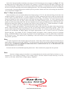
STEP 6 - INSTALL THE AIR LINE AND THE INFLATION VALVE
Uncoil the air line tubing and cut it into two equal lengths. DO
NOT FOLD OR KINK THE TUBING. Try to make the cut as square as
possible. Insert one end of the tubing into the straight fitting installed
in the top of the air helper spring. Push the tubing into the fitting as
far as possible refer to Figure "A".
Select a location on the vehicle for the air inflation valves. The
location can be on the bumper or the body of the vehicle, as long as
it is in a protected location so the valve will not be damaged, but maintain
accessibility for the air chuck, see Figure "D".
Figure "B"
AIR LINE
PUSH-TO-CONNECT
INFLATION VALVE
FLAT WASHER
HEX NUT
VALVE CAP
BODY OF
VEHICLE
Figure "E"
Figure "D"
HEAT SHIELD
Figure "C"