


WS-93002N page 3 of 7
Setting the SWICHGAGE
®
contacts
1. Face mounted contacts are set using a 1/16 in. hex wrench.
2. Some models such as 20PE, 20TE, etc. may not have field adjust-
ment. Consult the factory if in doubt.
3. Observe the “normal operating” oil pressure and coolant tempera-
ture readings. Set the oil pressure Swichgage contact slightly below
the minimum reading observed or slightly above the minimum
pressure recommended by the engine manufacturer.
4. Set the temperature Swichgage contact slightly above
the “normal
operating” temperature reading observed or slightly below the maxi-
mum temperature recommended by the engine manufacturer.
NOTE: More detailed instructions are contained in Installation Sheet
P-95033N for pressure Swichgage instruments and T-8446N for
Temperature Swichgage instruments.
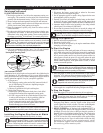
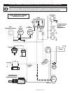
Testing the SwichgageInstruments
For face mounted contacts (20P, 20T, 20PW7, etc.):
1. With the engine running; use a
1
/16 in. hex wrench to rotate the con-
tact until it touches the gauge pointer. Do NOT force the contact
against the pointer. Engine should shut down and/or alarm should
operate. Reset the contact.
2. An alternative method of testing the
shutdown circuit is to place a coin
or other metal object between the
contact adjustment and the bezel.
NOTE: This method does NOT test
the actual contact pair. It does test the
circuit beyond the contact.
3. VER
Y IMPORT
ANT
Each time you
start the engine, observe that the Swichgage instruments are indicat-
ing pressure or temperature, etc. Visual inspection and regular test-
ing should be normal procedure to ensure proper operation and to
achieve maximum results from your Swichgage system.
WARNING: If the pressure Swichgage instrument has a
lockout push button on the face, a contact setting higher than the
factory setting will make the lockout device inoperative.
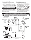
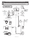
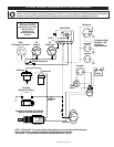
CAUTION: This wiring is typical for Murphy W-Series small engine panels. Items shown may or may not be included in your panel;
however, the circuit is typical of how the component will be wired if it is included. Refer to installation instructions for the specific
component if included. For off-panel items such as shutdown devices, see specific instructions supplied with the device.
TYPICAL WIRING DIAGRAM WITH 117PH MAGNETIC SWITCH
C
S
B
B
+
GRDSIG
_
+
Ignition coil
Distributor
Fuel Valve
Rack Pull Solenoid
(RP2300 Series shown)
Tachometer
Hourmeter
Voltmeter
117PH
20T
Temperature
20P
Pressure
Ammeter
Battery
_
+
_
+
_
+
ST
ACC
IGN
BAT
Start
Switch
Alternator
To Magnetic Sensor,
Alternator “Tach”
Terminal, or
Signal Generator
B
+
Energized
to Run
Model 117PH
Use for 12 or 24 VDC
PB128S Stop Switch
Other
Swichgage instruments
Starter
S
B
Exciter