


RP-95028B/N page 2 of 2
Mounting
1.
Mount the RP75 using a mounting bracket as illustrated in
Figure 1 (see page 1 of this bulletin for mounting hole dimen-
sions.). If installing the RP75 to an engine com-
partment firewall, go to Step 2.
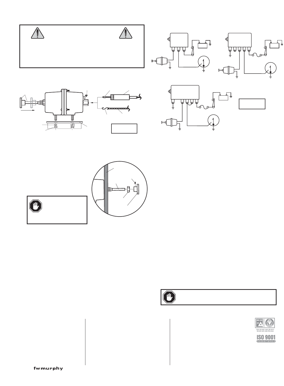
2.
If installing the RP75 to an engine
compartment firewall, drill a 37/64
in. (15 mm) diameter hole in the
firewall (see Figure 2).
3.
Remove the reset knob on the RP75 by loosening the allenhead
screw on the knob.
4.
Remove the mounting nut and insert the RP75 reset stem
through the hole from the back of the firewall.
5.
Replace the mounting nut and tighten. Reinstall the reset knob.
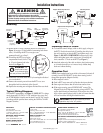
Typical Wiring Diagrams
Wire the RP75 appropriately (see Figure 3). NOTE: RP75 is voltage
rated; do not apply 24 VDC to 12 VDC model and vice versa. Also,
the 117PH Magnetic Switch is rated for both 12 and 24 VDC circuits
but voltage must be specified when ordering the 518PH or 761APH
Magnetic Switches.
Installing Cable or Chain
1.
To install the control linkage (cable or chain), apply voltage to
the RP75. Push in the reset knob. If installing the cable, insert
the cable attaching nut into the RP75 and tighten snugly (see
Figure 1). DO NOT OVERTIGHTEN or threads may strip.
Attach and tighten outer cable securing nut. If installing the
chain, attach the “S” hook to the RP75 (see Figure 1).
2.
Attach the other end of the cable or chain to the injection pump
or air intake shut-off lever so it moves freely without sharp
bends and without binding.
Operation Test
NOTE: Some method must be provided to disconnect (lockout) all
normally closed SWICHGAGE
®
circuits when starting (such as
through the appropriate Magnetic Switch).
1.
Reset magnetic switch.
2.
Push in RP75 reset stem until coil latches the trip mechanism.
3.
Start engine and observe that all locked out contacts clear.
4.
With engine running, ground SWICHGAGE
®
contact. The
Magnetic Switch will trip thus removing voltage to RP75. The
engine should shutdown immediately. If the engine does shut-
down, adjust control linkage (cable or chain) to ensure that shut-
off lever travels the full length in both directions.
RP75
Magnetic Switch Energized to Run
SWICHGAGE
®
CSB
Battery
117PH
RP75
Magnetic Switch Energized to Run
SWICHGAGE
®
GBSW1SW2N.C.
Battery
518PH
RP75
Time Delay On Start
SWICHGAGE
®
GBSN.O. N.C.
Battery
761APH
Installation Instructions
WARNING
Before beginning installation of this Murphy product:
✔✔
Disconnect ALL electrical power to the machine.
✔✔
Make sure the machine CANNOT operate during installation.
✔✔
Follow all safety warnings of the machine manufacturer.
✔✔
Read and follow all installation instructions.
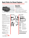
Mounting
Bracket
Lockwashers
(4 required)
1/4-20 Nut
(4 required)
Wiring
Terminals
Cable
Attaching Nut
Outer Cable
Securing Nut
“S” Hook
Chain
Reset Knob
and Stem
Push to Latch
Firewall
Reset
Knob
Mounting
Nut
Reset
Stem
Allenhead
Screw
Figure 1
Figure 2
Figure 3
CAUTION: Shut-off lever should not pull hard
against the stop in the “off” position.
WARNING
: The
firewall must be capa-
ble of withstanding the
push and pull force of the RP75.
CONTROL SYSTEMS & SERVICES DIVISION
P.O. Box 1819
Rosenberg, Texas 77471 USA
Phone: +1 281 633 4500 Fax: +1 281 633 4588
E-mail: sales@fwmurphy.com
FRANK W. MURPHY, LTD
Church Rd Laverstock
Salisbury SP1 1QZ UK
Phone: +44 172 241 0055 Fax: +44 172 241 0088
E-mail: sales@fwmurphy.co.uk
Web site: www.fwmurphy.co.uk
COMPUTRONIC CONTROLS, LTD
41 - 43 Railway Terrace Nechells
Birmingham B7 5NG UK
Phone: +44 121 327 8500 Fax: +44 121 327 8501
E-mail: info@computroniccontrols.com
Web site: www.computroniccontrols.com
FW MURPHY INSTRUMENTS (HANGZHOU) CO. LTD
77 23rd Street
Hangzhou Economic & Technological Development Area
Hangzhou, Zhejiang 310018 China
Phone: +86 571 8788 6060 Fax: +86 571 8684 8878
FW MURPHY
P.O. Box 470248
Tulsa, Oklahoma 74147 USA
+1 918 317 4100 Fax: +1 918 317 4266
E-mail: sales@fwmurphy.com
INDUSTRIAL PANEL DIVISION
Fax: +1 918 317 4124
E-mail: ipdsales@fwmurphy.com
MURPHY POWER IGNITION
Web site: www.murphy-pi.com
www. .com
Printed in U.S.A.