


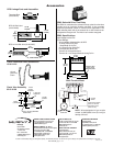
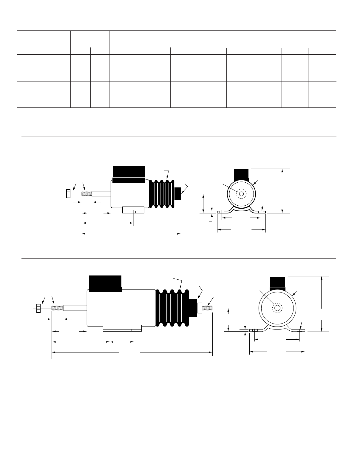
1/2 in.
(13 mm)
1-19/32 in.
(40 mm)
2-13/16 in.
(72 mm)
5 in.
(127 mm)
Boot
Internal
†
1/4-28
1 in.
(25 mm)
3/32 in.
(2 mm)
2 in.
(51 mm)
2-1/2 in.
(64 mm)
2-7/16 in.
(62 mm)
9/32 in.
(7 mm)
1-5/8 in.
Diameter
NOTE: Remove
or pierce decal
to install shaft.
1/4-28 Shaft w/nut
shown installed
(is supplied loose)
3/32 in.
(2 mm)
2 in.
(51 mm)
Diameter
2-1/16 in.
(52 mm)
3-9/32 in.
(83 mm)
1-1/2 in.
(38 mm)
7-7/32 in.
(184 mm)
Boot
Internal
†
1/4-28
1/4-28 Shaft w/nut
shown installed
(is supplied loose)
Shown with
stud and nut
installed.
1-1/8 in.
(28 mm)
3-1/8 in.
(79 mm)
2-1/2 in.
(64 mm)
9/32 in.
(7 mm)
2-7/8 in.
(73 mm)
21/32 in.
(17 mm)
Remove or
pierce decal
to install shaft.
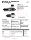
RP2307B and RP2308B
RP2309B and RP2310B
Solenoid Dimensions
Solenoid Shown with Plunger Seated (Coil Energized)
Solenoid Shown with Plunger Seated (Coil Energized)
†
A stud with nut is supplied, loose.
1-1/2 in. (38 mm)—1/4-28
part number: 40-01-0055
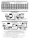
Solenoid
Model
Number
Maximum
Stroke
In. (mm)
Power in Watts
Seated Inrush
Force* in Pounds [Kilograms] at 100% Voltage**
Stroke in Inches (Millimeters)
Hold 1/8(3) 1/4(6) 1/2(13) 3/4(19) 1(25) 1-1/4 (32) 1-1/2(38)
Continuous
RP2307B 1 (25) 18 624
25 [11.34] 22 [9.98] 21 [9.53] 17 [7.71] 14 [6.35] 10 [4.54] — —
<13> [5.90] <12> [5.44] <11> [4.99] <10> [4.54] <8> [3.63] <6> [2.72] — —
RP2308B 1 (25) 12 696
27 [12.25] 25 [11.34] 23 [10.43] 19 [8.62] 15 [6.80] 11 [4.99] — —
<15> [6.80] <14> [6.35] <13> [5.90] <12> [5.44] <9> [4.08] <7> [3.18] — —
RP2309B 1-1/2 (38) 18 1029
32 [14.52] 30 [13.61] 27 [12.25] 22 [9.98] 18 [8.16] 13 [5.90] 8 [3.63] 6 [2.72]
<19> [8.62] <18> [8.16] <16> [7.26] <14> [6.35] <11> [4.99] <9> [4.08] <6> [2.72] <4> [1.81]
RP2310B 1-1/2 (38) 12 960
35 [15.88] 34 [15.42] 31 [14.06] 26 [11.79] 22 [9.98] 17 [7.71] 12 [5.44] 7 [3.18]
<20> [9.07] <19> [8.62] <17> [7.71] <15> [6.80] <12> [5.44] <9> [4.08] <7> [3.18] <4> [1.81]
*Forces shown are without return spring. Forces shown < > are with return spring. Forces shown in [ ] are in kilograms.
**To determine the operating current, divide the power (watts) indicated in the above table by the applied voltage.
Solenoids will operate at any stroke less than maximum.
†
A stud with nut is supplied, loose.
1-1/2 in. (38 mm)—1/4-28
part number: 40-01-0055
Watts Power/Cold Force in Pounds at 100% Voltage/Inches Stroke
RPS-00092B page 2 of 4
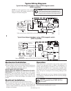
Note 1. Typical operating temperature for single 15 second operation of the energize coil is less than:
140°F(60°C) ± 10°F (6°C) for 1 in. (25 mm) Stroke Solenoids (70°F/21°C Rise above ambient)
120°F(49°C) ± 10°F (6°C) 1-1/2 in. (38 mm) Stroke Solenoids (50°F/10°C Rise above ambient)
See CAUTION statement on next page and note maximum housing temperature is 185°F (85°C).
Note 2. The energize-coil should not be activated for more than 15 seconds.
Longer energize-coil activation times will damage the solenoid.
Note 3. Allow minimum 15 minutes for cooling between activations of energize-coil to avoid damaging the
solenoid. (Depends on length of time energize coil is energized.)
Note 4. The energize-coil must fully seat the plunger to allow the hold-coil to function properly.