


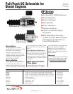
RPS-00092B page 3 of 4
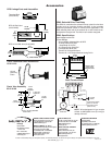
Mechanical Installation
1.Bolt the solenoid securely to the mounting bracket.
2.Connect linkage and check for binding. Plunger should move
freely throughout the complete stroke and be allowed to
“bottom” at the internal stop of the solenoid.
DO NOT MOUNT WITH BOOT DOWN.
DO NOT APPLY ANY GREASE OR LUBRICATION TO PARTS.
IMPORTANT: If the plunger does not seat, it will release
prematurely when shifted to the “holding” mode of operation.
Readjust linkage to lengthen the plunger stroke. Adjust the yoke
in increments of 1/2 turn until plunger will remain in hold
position.
Electrical Installation
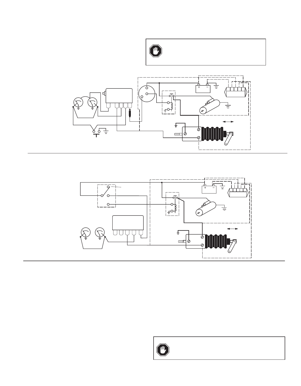
1.Refer to the diagrams above for typical electric wiring.
2.Use minimum 10 AWG [65/0.3 mm (4.5 mm)] wire size, as
noted in the wiring diagrams. A smaller wire will reduce the
current available and thus the pulling force. Wire length must
be kept to a minimum.
Operation
The solenoid coil is connected to the existing engine starter
system or an equivalent circuit. A SD85 is recommended. At
starting, both the Energize and Hold-in coils are energized. In
the run mode, the Hold-in coil is continuously energized while
the Energize coil has to be disconnected, reducing the heating
effect and power consumption and avoiding damage to the
device.
NOTE: Coils that burn out due to improper electrical hookup,
misadjustment or improper operation are not covered by Murphy
factory warranty.
NOTE: A cool down period of 15 minutes minimum should be
allowed between energized pull in cycles.
Energize
Hold
G NC
SW
1
B
SW
2
IG
ST
20P-F 20T-F
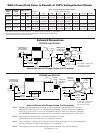
Typical Closed Loop™ Circuit
Emergency
Stop
Starter Contactor
Relay
RP2300 Series
Solenoid
Fuel Lever
Battery
10 AWG
*
10 AWG
*
SWICHGAGE
®
Instruments
518PH
TATTLETALE
®
Start Key
Switch
In-Line
Fuse
B
10 AWG
*
10 AWG
*
ON OFF
Starter
Motor
N.O.
12345
SD85
NO BNC
Energize
N.O.
Hold
OFF
ON
START
20P
20T
SG
ON OFF
Battery
10 AWG
*
10 AWG
*
10 AWG
*
10 AWG
*
RP2300 Series
Solenoid
Fuel Lever
Starter
Motor
Starter Contactor
Relay
760A
Time-Delay
Before Shutdown
Turn OFF for
Emergency Stop
Existing
Start
System
SWICHGAGE
®
Instruments
Key Switch
OFF: No power.
ON: Power to hold coil of
fuel solenoid.
START: Power to energize
coil of fuel solenoid.
12345
SD85
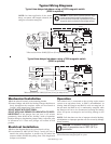
*Wires must be minimum 10 AWG (65/0.3 mm [4.5 mm]) to develop full force.
*Wires must be minimum 10 AWG (65/0.3 mm [4.5 mm]) to develop full force.
Typical Wiring Diagrams
CAUTION: The solenoid housing is hot to the
touch. A temperature rise to 185°F (85°C) is
permissible.
Typical time-delayed shutdown using a 760A magnetic switch
(SD85 is optional)
NOTE: In either application if the starter
hangs, on starters with integral solenoids, the
energize coil remains energized.
CAUTION: On certain starter solenoids/contactor relays,
current can feed back through the energize terminal
from the hold coil and provide a parallel path to ground
through the device connected to the energize terminal.
Typical time-delayed shutdown using a 518PH magnetic switch
(SD85 is optional)