


MT-9004B page 2 of 2
100's 10's 1's
0
1
2
3
6
9
4
5
7
8
0
1
2
3
6
9
4
5
7
8
0
1
2
3
6
9
4
5
7
8
X 1000 X 100 X 10
2
3
4
5
Magnetic
Pickup
Locknut
Hole Drilled and
Tapped, Bolt Thread
NOTE: Gap from face of gear tooth must be enough for gear to move. Rotate gear completely
to be sure of minimum, no-touch clearance. See instructions supplied with the magnetic sensors.
To get minimum of 4 VAC RMS, gap tolerance is critical. Turn the pickup in until it stops against
the face of a gear tooth. Back the pickup out only enough to allow rotation of the gear. Rotate the
gear, if any tooth touches the pickup, back it out to clear the tooth. After clear rotation secure the
pickup locking nut.
MT90
with
customer
wiring
0
1
2
3
6
9
4
5
7
8
0
1
2
3
6
9
4
5
7
8
0
1
2
3
6
9
4
5
7
8
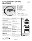
When calibrating for use with a magnetic
pickup, dial in the number of flywheel teeth
or pulses per revolution: for example, if the
flywheel has 125 teeth then dial in125.
See Calibration for alternator installation.
6
Magnetic Pickup Powered MT90
(No back-lighting)
Magnetic Pickup
Locknut
Hole Drilled and
Tapped, Bolt Thread
NOTE: Gap from face of gear tooth must be enough for gear to move. Rotate gear completely
to be sure of minimum, no-touch clearance. See instructions supplied with magnetic sensor.
100's 10's 1's
0
1
2
3
6
9
4
5
7
8
0
1
2
3
6
9
4
5
7
8
0
1
2
3
6
9
4
5
7
8
X 1000 X 100 X 10
Battery
12V-24V-32V
Alternator
When calibrating for use with a magnetic
pickup, dial in the number of flywheel teeth
or pulses per revolution: for example, if the
flywheel has 125 teeth then dial in125.
See Installation and Calibration for alternator
installation.
2
3
4
5
Back-light
ON/OFF
MT90
with
customer
wiring
0
1
2
3
6
9
4
5
7
8
0
1
2
3
6
9
4
5
7
8
0
1
2
3
6
9
4
5
7
8
Tachometer
Terminal
NOTE:
Alternator
must be
equipped
with a Tach.
terminal
(auxiliary
AC terminal).
*
*
6
Battery Powered MT90
(With back-lighting)
MP3298
Terminal 2: connects to battery (-) or ground.
Terminal 3: connects the back-light to battery (+), (back-light can only be used
when powering from battery).
Terminal 4: connects to battery (+) or power from magnetic pickup or alterna-
tor.
Terminal 5: RPM input signal from magnetic pickup.
Terminal 6: RPM input signal from alternator.
Typical Wiring Diagrams for MT90
Magnetic Pickups
Calibration
To calibrate the MT90 for your engine, remove the rubber seal on the
back of the tachometer and dial in the correct number.
• Magnetic Pickup: dial in the number of teeth on your ring gear.
Set the switches from left to right. For example, if the engine gear
has 125 teeth, dial a 1 on the left switch, a 2 on the center switch,
and a 5 on the right switch. Using this setting, the MT90 will
count the passing teeth and convert them into engine RPM.
• Alternator: Multiply the ratio of alternator to engine pulley dia-
meter, times, the number of poles of the alternator divided by two,
to determine the correct calibration number (also see “Other
Calibration Methods”).
Other Calibration Methods (teeth or ratio unknown)
For setting the calibration switches when the number of pulses per
revolution are not known, set the rotary switches on back of the MT90
to 0-6-0 and read the tachometer at a known engine RPM. This can be
read by a hand-held tachometer or any means which tells actual RPM
The reading is the input frequency in hertz. Multiply the frequency
times 60 and divide the result by the engine RPM. Set this number into
the rotary calibration switches. NOTE: If pulses per revolution are not
a whole number, for example: 21.5, a setting of 021 will read slightly
high and a setting of 022 will read slightly low.
To order a MT90 for your application, use the diagram below.
MT90 – ___ – ___
How to Order
Bezel
Blank = Bright stainless
B = Black stainless
Face Plate
1 = White background
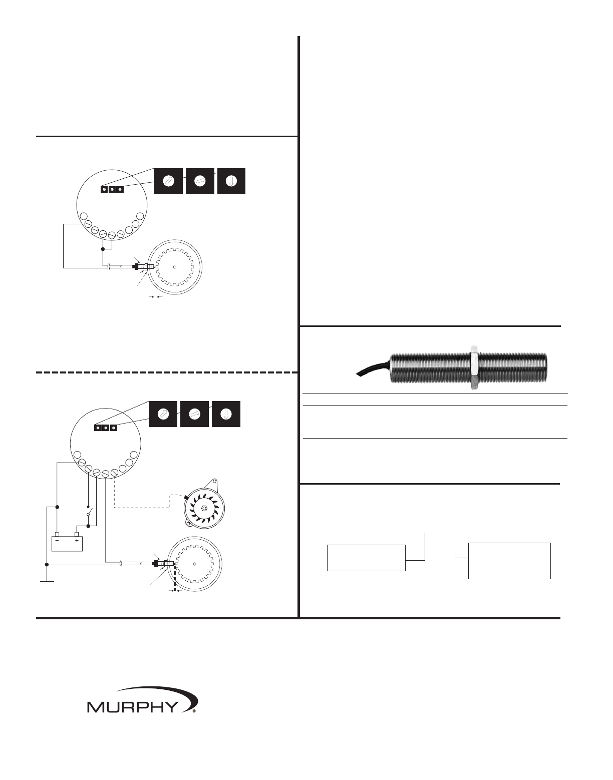
To order a magnetic pickup, specify model number.
Example: MP3298
Pickup Models Total Length Threaded Length Thread Size
MP3298* 3 in. (76 mm) 3 in. (76 mm) 5/8-18 UNF
MP7906
†
3 in. (76 mm) 3 in. (76 mm) 3/4-16 UNF
MP7905
††
4-1/2 in. (114 mm) 4-1/2 in. (114 mm) 3/4-16 UNF
*
Replaces 20-01-0080 and MP100. Lead wire hookup (12 in. [305 mm]).
†
Replaces 20-01-0081. Lead wire hookup (12 in. [305 mm]).
††
Replaces 20-01-0082. Lead wire hookup (12 in. [305 mm]).
In order to consistently bring you the highest quality, full featured products, we reserve the right to change our specifications and designs at any time.
Printed in U.S.A. 0290998
In order to consistently bring you the highest quality, full featured products, we reserve the right to change our
specifications and designs at any time. MURPHY, the Murphy logo, and Selectronic
®
are registered and/or com-
mon law trademarks of Murphy Industries, Inc. This document, including textual matter and illustrations, is copy-
right protected by Murphy Industries, Inc., with all rights reserved. (c) 2006 Murphy Industries, Inc.
www.fwmurphy.com
918.317.4100 Email: sales@fwmurphy.com