


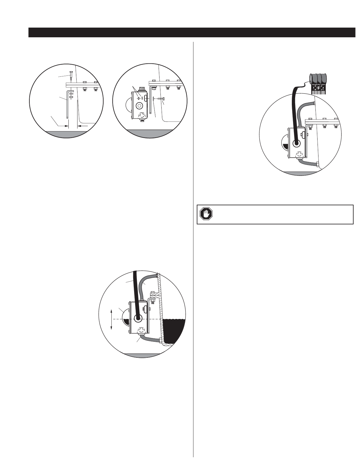
Crankcase (Oil Pan) Mounting
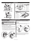
1. Install the universal bracket to the crankcase using the existing crankcase bolts
(Figure 3A). Crankcase bolt diameter must be no larger than 7/16 inch (11 mm).
NOTE: Check clearance between crankcase and mounting bracket
before installing the mounting bracket. If space between the crankcase
and mounting bracket does not allow installation and access to the
adjustment bolts advance to Step 3.
2. Mount the LM2000 to the universal bracket using two 1/4-20 UNC x 1-
1/4 inch bolts, nuts and lock washers supplied. DO NOT tighten the
adjustment bolts too tight. You will have to adjust the LM2000 later in the
installation process.
3. If space between the crankcase and mounting bracket is narrow, install the uni-
versal mounting bracket to the LM2000 before installing to the crankcase oil pan.
Connecting Fittings and Hoses
The following instructions are based on the Murphy optional hose kit
described on page 1. If you did not order the optional hose kit, use the
list designation as a guide to the required materials.
1. Install the LM2000 fittings in their proper locations. NOTE: Apply a
sealant such as Teflon
®
, to all threaded
connections.
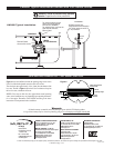
2. Attach the 1 inch (25 mm) diam-
eter, flexible monitoring hose
to the crankcase and the mon-
itoring port on the LM2000.
See Figure 4. CAUTION:
The hose must slope slightly
downward from the LM2000
and MUST NOT have any
droops or low spots.
NOTE: If the drain plug on the
crankcase is used for the connection, we
recommend installation of a tee to allow
draining of the crankcase for service.
3. Install the 1/2 inch (13 mm) I.D. x 3 ft. (914 mm) hose to the vent connec-
tion on the LM2000 and to the vent connection on the crankcase. See
Figure 4. The vent connection on the crankcase must be well above
the regulated oil level. All hoses must be clear of obstructions, valleys,
or dips that could create liquid traps, or gas/air pockets. The vent and
crankcase connections should be as straight as possible.
BEFORE CONTINUING, VERIFY THAT ALL HOSE CLAMPS ARE TIGHT.
4. Fill the crankcase to the proper oil level. With the engine running and
warm, loosen the mounting bracket adjustment bolts and adjust the
LM2000 so that the oil level in the sight gauge is aligned with the white
“index line” on the dial (Figure 4). Tighten the adjustment bolts securely.
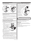
Connecting the LM2000 to an Oil Supply Tank
1. Remove the plug from the oil inlet connection. Be sure the removable screen,
inside the connection, is clear of debris. Install the oil inlet connection.
2. Connect a 1/2 inch I.D. (13 mm) or larger hose
to the oil inlet fitting on the LM2000 and to the
shutoff valve on the oil supply tank. See
Figure 5. Recommended minimum
height above the LM2000 is 2 ft.
(0.6m); maximum 25 ft.
(7.7m). The hose must
maintain a downward
slope and not have low
spots or droops.
Maximum head pressure
rating is 9.50 psi or 25 ft
oil (head pressure).
3. Before filling the supply
tank with oil, be sure the
tank is clean and dry and
the shutoff valve is closed.
Also, be sure all hoses and clamps are tight. Fill the tank with CLEAN
oil.
4. After oil supply tank is full, open the shutoff valve.
Next, make the proper electrical connections for the application.
(See Snap-switch ratings and schematic on page 1.)
Switch Test
To test the shutdown or alarm functions perform the following:
NOTE: Installations with closed vent systems can only be tested with
the engine off.
1. Unscrew the vent fittings.
2. Using a long narrow shank screw driver, gently insert until contact is
felt with float arm. Gently push the float arm down.
3. Verify proper switch operation
LM-00011N page 3 of 4
TYPICAL INSTALLATION
Figure 3B
Crankcase
Universal
Bracket
Crankcase
Bolt
Note Clearance
before mounting
Adjustment
Bolt
Flat
Washer
Lock washer
and Nut
Figure 3A
Oil Inlet
Hose
Oil Supply
Tank
Figure 5
Viewing
Lens
Monitoring Hose
Crankcase
Oil Level
Running
Engine
Vent
Hose
Oil Inlet
Hose
Figure 4
WARNING: Overfill condition can be caused by excessive
inlet pressure and/or improper “vent to crankcase” installation.