


Section 78 00-02-0629
08-08-07 - 7 -
Installing an NMEA 2000
®
Network
Installing an NMEA 2000
consists of interconnecting NMEA 2000 electronic devices using
plug-and-play cables and connectors. The following pages provide a brief description of how
to setup a NMEA 2000 network using five basic steps:
1. Cable and Connector Network Basics
2. Installing Terminators
3. Supplying Power
4. Grounding the Network
5. Checking the Network
Please note that this installation guide contains a brief description of the basic concepts of
installing an NMEA 2000 network. You can learn more about installing NMEA 2000 networks
by contacting the National Marine Electronics Association (NMEA) at www.nmea.org and
consulting the following documents:
• NMEA 2000 Standard for Serial-Data Networking of Marine Electronic Devices
• NMEA Installation Standards
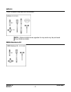
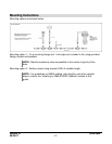
Cable and Connector Network Basics
Network Topology
The NMEA 2000 cable system uses a trunk (sometimes referred to as the backbone), drop
line, drop tee, and termination resistor.
The NMEA 2000 cable system includes five wires within a single waterproof cable: two signal
wires, power and ground wires, and a drain wire. The drain wire shields the signal, power, and
ground wires from external Radio Frequency Interference (RFI) and helps reduce RFI emission
from the cable.
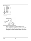
Maximum Cable Distance
The cable distance between any two points in the cable system must not exceed 100 meters
(328 feet) for the Micro cable.
Maximum Drop Line Length
The maximum cable distance from any device on a branching drop line to the trunk link is 6
meters (20 feet).