


The overspeed set point switches are available on the DT9805 and
DT9806 only. The overspeed set point can be set within ± 5 RPM, over a
range of 0010 to 9990 RPM. Setting of the overspeed set points is made by
properly adjusting of three rotary switches. Each switch can be adjusted in
increments of ten. To set the switches perform the following:
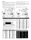
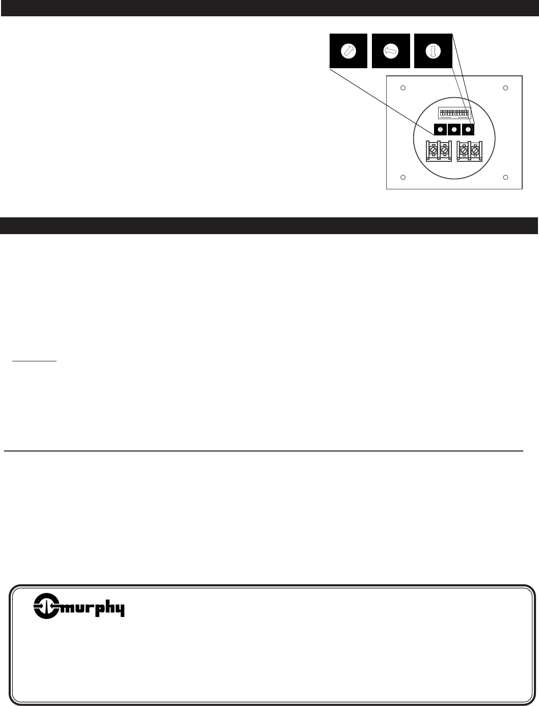
1. Locate the three rotary switches on the back of the unit (Figure 8).
2. Insert a small blade screwdriver inside the arrow slot. Turn the
screwdriver until the arrow pointer is facing the number you choose.
EXAMPLE: You want the overspeed to trip at 1850 RPM (Figure 8):
(1) Rotate the X-1000-arrow to the (1),
(2) Rotate the X-100-arrow to the (8),
(3) Rotate the X-10-arrow to the five (5).
0
1
2
3
6
9
4
5
7
8
0
1
2
3
6
9
4
5
7
8
0
1
2
3
6
9
4
5
7
8
X 1000 X 100 X 10
0
1
2
3
6
9
4
5
7
8
0
1
2
3
6
9
4
5
7
8
0
1
2
3
6
9
4
5
7
8
Figure 8:
Overspeed switch
set at 1850 RPM
SETTING OVERSPEED SET POINTS: DT9805 AND DT9806
DT9804 AND DT9806 TROUBLESHOOTING
If the DT9804 or DT9806 tachometer reading is incorrect or erratic follow
the steps below in order until the devices read properly.
1. Check for proper voltage for your ignition system (90-150).
2. Check all grounds, be sure they are good and tight.
3. Separate ignition wires from primary coil wires.
4. Check switches for correct settings according to the number of engine
cylinders. Where the ignition system has two storage capacitors, the
tachometer must be set for half the number of engine cylinders.
DO NOT USE A PENCIL TO PUSH SWITCHES
.
5. Check reading on 110 VAC 60 Hz with all switches open or on 0. The
display should read all 0's. Also refer to the calibration chart in step 9.
6. The shutdown lead must be separated at least 12 in. (305 mm) from the
high-tension spark plug leads. The best practice is to run the shutdown
lead from the junction box to the panel in a separate conduit.
7. The common ground for the capacitor discharge ignition system coils
must be grounded to the engine block, preferably as close to each coil
as possible.
8. If the Murphy adaptor package is used make sure the tach is connected
to the input (ALT 1, ALT 2) not the output.
9. Calibration Check: Hook 110 VAC 60 Hz hot to the input 90-150 and
the neutral to the negative input. These readings are ±1 RPM.
Dip Switches On Reading
2, 4, 5 60
1, 5, 9 639
3, 6, 10 1284
2, 8, 11 2704
1, 7, 12 4951
056499
4
Warranty
A two-year limited warranty on materials and workmanship is given with this
Murphy product. Details are available on request and are packed with each unit.
Printed in U.S.A.
®
FRANK W.
MFR.
■ Frank W. Murphy Manufacturer
P.O. Box 470248; Tulsa, Oklahoma 74147; USA
tel. (918) 627-3550 fax (918) 664-6146
e-mail fwmurphy@ionet.net
■ Frank W. Murphy Southern Division
P.O. Box 1819; Rosenberg, Texas 77471; USA
tel. (281) 342-0297 fax (281) 341-6006
e-mail murphysd@intertex.net
Since 1939
■ Frank W. Murphy, Ltd.
Church Rd.; Laverstock, Salisbury SP1 1QZ; U.K.
tel. +44 1722 410055 fax +44 1722 410088 tlx 477088
e-mail sales@fwmurphy.co.uk
■ Frank W. Murphy Pte., Ltd.
26 Siglap Drive; Republic of Singapore 456153
tel. +65 241-3166 fax +65 241-8382
e-mail fwmsales@fwmurphy.com.sg
■ Murphek Pty., Ltd.
1620 Hume Highway; Campbellfield, Vic 3061; Australia
tel. +61 3 9358-5555 fax +61 3 9358-5558
In order to consistently bring you the highest quality, full featured products, we reserve the right to change our specifications and designs at any time.
■ Murphy de México, S.A. de C.V.
Blvd. Antonio Rocha Cordero 300, Fracción del Aguaje
San Luis Potosí, S.L.P.; México 78384
tel. +52-48-206264 fax +52-48-206336
e-mail murmexsl@sanluis.podernet.com.mx
■ Murphy Switch of California
P.O. Box 900788; Palmdale, California 93590; USA
tel. (805) 272-4700 fax (805) 947-7570
e-mail sales@murphyswitch.com
■ Frank W. Murphy France
tel. +33 1 30 762626 fax +33 1 30 763989