


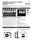
DT9805
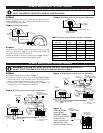
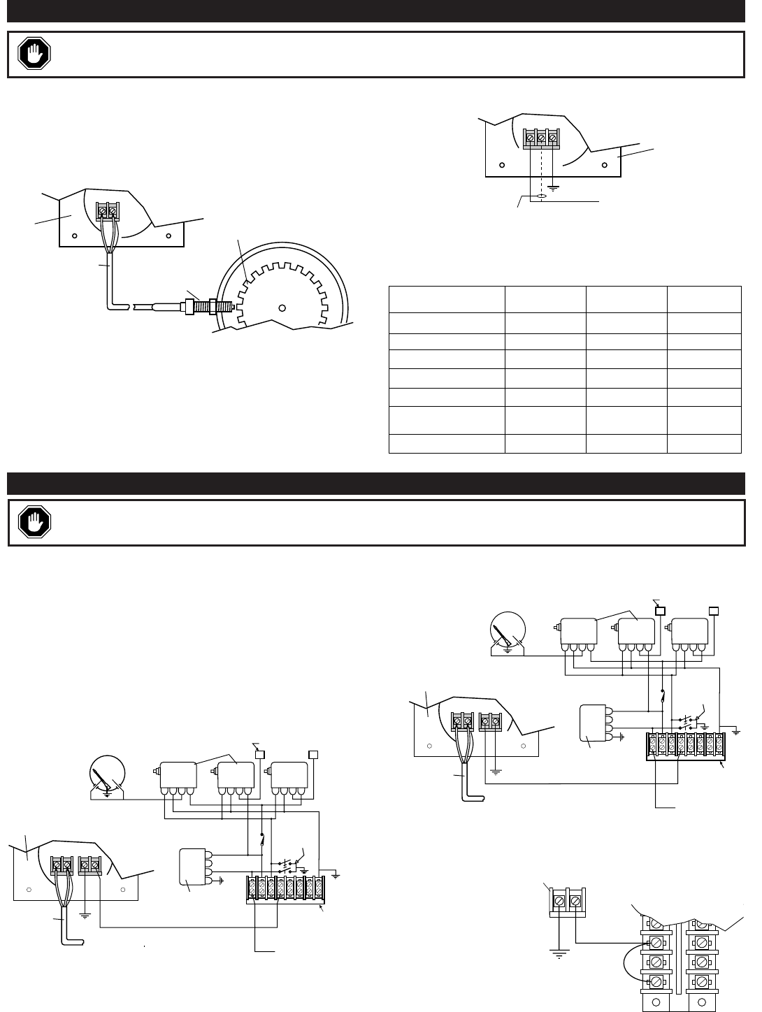
1. Connect the magnetic pickup as shown in Figure 3.
2. Connect the overspeed switch wiring as shown Figures 3 and 4.
Observe the polarity of the overspeed switch. The positive terminal
must be connected to the positive side of the circuit as shown.
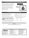
3. If connecting to a Murphy LCDT annunciator refer to Figure 5. See
General Catalog for more information on the LCDT.
1 G23
SW
ALT 2
ALT 1
GRD
Pressure Overspeed Level
123
12345678
45
To Negative Ground
CD Ignition
Adapter
Package
Emergency
Stop Switch
Frame
Ground
Connected to
Corresponding Numbers
On Terminal Block Below
307-PH-CD
TATTLETALE
®
Connect to
Good Engine
Ground
2 Conductor
Shielded Cable
Belden or
Equivalent
To Magnetic Pickup
NEG
POS
MPU OS
Back of
DT9805
SWICHGAGE
®
Figure 3:
DT9805 typical wiring for negative ground ignition
DT9803 AND DT9804 TYPICAL WIRING
2
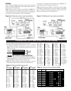
DT9803
Connect the magnetic pickup cable conductors to the MPU terminal as
shown in Figure 1. Use a two conductor shielded cable between the
DT9803 and the magnetic pickup.
DT9804
Before wiring the DT9804, determine the output voltage and ground
polarity of the ignition. Table 1 lists the Peak Output Voltage and
Ground Polarity of some common ignitions.
Connect the DT9804 tachometer to the CD ignition. Figure 2 shows a
typical wiring diagram for negative ground ignition system.
1 G23
SW
ALT 2
ALT 1
GRD
Pressure Overspeed Level
123
12345678
45
To Positive Ground
CD Ignition
Adapter
Package
Emergency
Stop Switch
Frame
Ground
Connected to
Corresponding Numbers
On Terminal Block Below
307-PH-CD
TATTLETALE
®
Connect to
Good Engine
Ground
2 Conductor
Shielded Cable
Belden or
Equivalent
To Magnetic Pickup
POS
MPU OS
NEG
Back of
DT9805
SWICHGAGE
®
Figure 4:
DT9805 typical wiring for positive ground ignition
Magnetic Pickup
2 Conductor
Shielded Cable
Belden or
Equivalent
Back of
DT9803
Flywheel
MPU
Figure 1:
DT9803 typical wiring
Optional Connection for
150-400 V Ignitions
Negative Ground Ignition
90-150
NEG
150-400
Back of
DT9804
Figure 2:
DT9804 typical wiring for negative ground ignition
Ignition
MFG & Series
Ground
Polarity
Peak Output
Voltage
Use Figure
Altronic I, III, & V Negative 120 6
Altronic II Positive 350 7
Bendix S-1800, BLAR Negative 250 6
Bendix Side-winder Positive 300 7
Fairbanks Morse SCSA Positive 180 7
Fairbanks Morse
3000 & 9000
Negative 225 6
American Bosch Magtronic
Negative 165 6
Table 1:
Output Voltage & Polarity of Common CD Ignitions
DT9805 AND DT9806 TYPICAL WIRING
WARNING
:
PERFORM THE WIRING INSTALLATION WITH THE POWER SOURCE OFF. DO NOT
ROUTE TACHOMETER LEADS WITH PRIMARY IGNITION WIRING.
WARNING
:
PERFORM THE WIRING INSTALLATION WITH THE POWER SOURCE OFF.
DO NOT ROUTE TACHOMETER LEADS WITH PRIMARY IGNITION WIRING.
46
50
NEG
POS
Overspeed
Switch Terminals
on DT9805 or DT9806
Murphy LCDT
Annunciator
Terminal Block
Figure 5:
DT9805 and DT9806
negative ground
connection to Murphy
LCDT (for positive ground
ignitions, reverse the
negative and positive wires
on the tachometer so that
the positive terminal is grounded.)