


Installation AT-04060N page 2 of 2
When applying the AT03069, please consider the operating environ-
ment. The case is designed to shed water from the top, but will collect
water if mounted upside down. The control linkage has been specially
designed to isolate vibration from the gear motor on the throttle actuator
directly to the outer case. this control linkage must be used or vibration
may seriously damage the internal gear motor. The flex linkage assem-
bly has been removed for shipping and must be installed before use. The
flex linkage assembly may be installed in the right or left hand slots on
the sides of the throttle actuator. The AT03069 must be mounted close
to, and in line with, the throttle block for straight line pull between the
lever arm and the butterfly lever arm.
NOTE: The throttle actuator should be mounted in a manner that
minimizes the effects of excessive shock and vibration on the unit.
A separate throttle block must be used if the engine is equipped with a
governor or a manual control wire. The AT03069 is not designed to
override other controls. The butterfly valve must work freely.
Typical Wiring
1. Connect terminal #1 to battery (+).
2. Connect terminal #4 to battery (-).
3. Advance the lever arm to the full idle RPM position (fully clockwise or counter-
clockwise by grounding #2 or #3 -- See above at left.)
4. Connect the flex linkage wire to the butterfly lever arm. Alternately ground terminal
#2 and #3 to determine the direction of travel. Select the proper mounting hole in
the lever arm of the AT03069 and on the throttle block butterfly arm to provide
proper travel. The proper throttler travel is from the mechanical set idle point, to
just slightly above the point where the mechanical governor limits the engine RPM.
5. Visually inspect the linkage assembly to insure that there are no sharp bends or
kinks. If the linkage wire bows during operation, a center support should be added.
6. After correct travel is established, tighten the set screws and linkage assembly.
NOTE: The lever arm must be allowed to travel its full arc. This allows the unit to
disconnect itself with internal limit switches. If the lever is unable to reach limit
switches, Damage to the unit can occur.
INSTALLATION and WIRING
IMPORTANT:
The AT03069 works on both 12 and 24 VDC systems. System volt-
age should be between 11 and 28 VDC. Exceeding 28VDC can cause damage. The
automatic throttle controller is used by alternately grounding terminals 2 and 3 to
maintain the desired engine RPM. The AT03069 is typically used to automatically adjust the
engine speed to maintain a desired discharge pressure on an engine-driven pump.
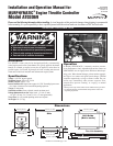
AT03069
Back View
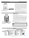
AT03069
Front View
Battery (+)
1234
Battery (-)
Battery (-) Causes
Shaft to Rotate
Counter-Clockwise
Battery (-) Causes
Shaft to Rotate
Clockwise
A second swivel is provided for
use on the butterfly valve lever arm.
Flex-linkage Assembly
CONTROL SYSTEMS & SERVICES DIVISION
P.O. Box 1819; Rosenberg, Texas 77471; USA
+1 281 633 4500 fax+1 281 633 4588
e-mailsales@fwmurphy.com
MURPHY DE MEXICO, S.A. DE C.V.
Blvd. Antonio Rocha Cordero 300, Fracción del Aguaje
San Luis Potosí, S.L.P.; México 78384
+52 444 8206264 fax +52 444 8206336
Villahermosa Office +52 993 3162117
e-mailventas@murphymex.com.mx
www.murphymex.com.mx
FRANK W. MURPHY, LTD.
Church Rd.; Laverstock, Salisbury SP1 1QZ; U.K.
+44 1722 410055 fax+44 1722 410088
e-mailsales@fwmurphy.co.uk
www.fwmurphy.co.uk
MURPHY SWITCH OF CALIFORNIA
41343 12th Street West
Palmdale, California 93551-1442; USA
+1 661 272 4700 fax+1 661 947 7570
e-mailsales@murphyswitch.com
www.murphyswitch.com
In order to consistently bring you the highest quality, full featured products, we reserve the right to change our specifications and designs at any time.
MACQUARRIE CORPORATION
1620 Hume Highway
Campbellfield, Vic 3061; Australia
+61 3 9358 5555 fax+61 3 9358 5558
e-mailmurphy@macquarrie.com.au
FW Murphy
P.O. Box 470248
Tulsa, Oklahoma 74147 USA
+1 918 317 4100
fax +1 918 317 4266
e-mail sales@fwmurphy.com
www.fwmurphy.com
R
E
G
I
S
T
E
R
E
D
USA–ISO 9001:2000 FM 28221
UK–ISO 9001:2000 FM 29422
Printed in U.S.A.
Warranty
A limited warranty on materials and workmanship is given with this FW Murphy product.
A copy of the warranty may be viewed or printed by going to www.fwmurphy.com/support/warranty.htm