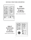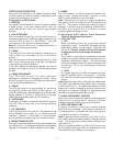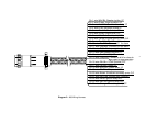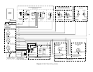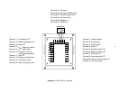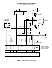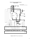
FRONT PANEL DESCRIPTION
Along with each description, an attempt has been made
to clarify output and input connections according to their
functions and terminals or wire color.
A. Description of LED Callouts
1. IGNITION
The ignition LED will come on when the system receives
a signal to start. If the alarm before start is used, this
ignition LED will NOT come on until the 5 second alarm
goes off.
2. PICKUP PRESENT
When the engine is cranking or running and the pickup is
connected properly with sufficient output voltage (2 volt
rms) this LED will come on. IMPORTANT - This LED
must come on or the unit will not operate properly.
Note: this LED will NOT be on if a mechanical switch is
used as a crank disconnect sensor.
3. CRANK
The crank LED is on when the engine is cranking and is
used to show that the crank circuitry is functioning
properly.
The crank solenoid will be connected to terminal 1 of the
A88-F or the white/brown wire of the A88, if the solenoid
is connected to positive to operate.
If the crank solenoid is grounded to operate, connect it to
terminal 2 of the A88-F or connect it to the white/red wire of
the A88.
4. CRANK DISCONNECT
This LED comes on when the crank disconnect
adjustment is adjusted to disengage the starter. When
this LED comes on, the crank LED goes out. (See item B-
2 for control setting adjustments)
5. CHOKE
This LED will come on for approximately 3-4 seconds at
the beginning of each crank cycle and then go out. If a
choke or compression release solenoid is connected from
battery positive to Terminal 3 (A88-F)or the violet wire
(A88) it will be energized when the LED comes on.
6. OVERCRANK
If the engine is called on to start and fails after 5 tries, this
LED will come on and stay on to indicate cause of
shutdown.
7. OIL PRESSURE
The oil pressure LED will come on if oil pressure is lost
during operation and remain on to indicate cause of
shutdown. Terminal 11 of the A88-F or the black/white
wire of the A88 are connected to the oil pressure switch.
8. ENGINE TEMPERATURE
If the unit is shutdown because of high engine temperature,
this LED will be on. The temperature sensor is connected to
Terminal 12 of the A88-F or the blue/white wire of the A88.
9. SPARE
This LED comes on to indicate cause of shutdown if the
spare is used. Connect the monitor to Terminal 13 of the
A88-F and the yellow/white wire of the A88.
Note: the overcrank, oil pressure, engine temperature
and spare circuits are locked out for 30 seconds during
start up. They require normally open sensors (close to
operate). A summary output is available (Terminal 20 on
the A88-F and the brown wire of the A88.) for remote
indication when a shutdown occurs.
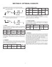
B. Description of AOT Switch, Crank Disconnect
Control & Rest/Crank Time Control
1. AUTO-OFF-TEST
a. OFF
When a shutdown occurs, this unit must be removed
from power to reset. The Auto-Off-Test switch removes
power when placed in the off position. The green LED
will go off. The unit should be left off 8-10 seconds
to allow the circuitry to discharge and stabilize.
b. TEST
This position is used after all connections have been
made or for periodic checks that should be a part of a
preventive maintenance program. The start and stop
inputs are by-passed when this switch is placed in the
test position. The unit will automatically initiate the
crank cycle.
c. AUTO
For normal operation and after the system has been
tested, Place the switch in this position. It indicates
the controller will take over starting and stopping the
engine.
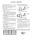
Note: these units may have a 4-5 second alarm before start.
The A88-F comes with the alarm hooked up by connection
of terminals 16 and 17. The A88 comes without the alarm
hooked up; if alarm is needed, ground the red/white wire.
Although it is an optional hook up, it is recommended that
this alarm be used to alert personnel of a start.
2. CRANK DISCONNECT CONTROL
Adjust this control to make the crank circuit disengage the
starter when the engine starts. Rotating it counter-
clockwise makes the starter drop out at lower RPM.
3. REST AND CRANK TIME
By placing this switch in one of the 4 positions, the rest
and crank time is selected. If the switch is placed in the
10 seconds position, the system will crank the engine for
10 seconds, then rest for 10 seconds.
Note: if the engine starts momentarily, then dies, it will go
into a 25-30 second rest period before it attempts another
crank. This is regardless of what position the crank and
rest switch is in.
When the system is called on to crank the first crank cycle
will be typically 50% longer than the remaining four tries.
This feature will aid in starting a cold engine.
3


