PAGE 20 — MQ SP4030 SAW • OPERATION MANUAL — REV. #0 (01/22/09)
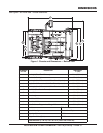
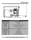
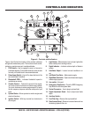
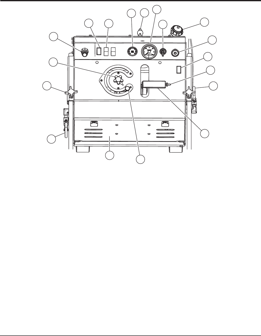
Figure 4. Controls and Indicators
CONTROLS AND INDICATORS
1
2
4
3
11
10
13
17
14
16
7
15
6
5
9
8
18
12
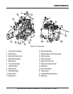
Figures 4 and 5 show the location of the controls, indicators
and general maintenance parts. The function of each control,
indicator or maintenance part is explained below:
1. FNR Handle – Use to engage the saw in a forward or
backward direction. Push handle forward to move the saw
forward; pull handle back to move saw backward.
2. Raise/Lower Switch –
Use to lift or lower the front of the
saw (and blade if installed).
3. Bladeshaft RPM –
Indicates bladeshaft speed in
revolutions per minute.
4. Throttle Control – Controls the speed of the engine.
Turn knob counter-clockwise to increase engine speed.
Turn knob clockwise to reduce engine speed. For quick
throttle response, depress red button and push or pull
knob.
5. System Status – Allows operator to monitor engine and
electrical functions.
6. Ignition Switch – With key inserted turn clockwise to
start engine.
7. Light Switch – When activated, turns on light. Lights offer
better visibility when working indoors.
8. Depth Indicator – Indicates relative depth of blade in
surface.
9. Handlebar Adjust –
Loosen to move handlebar in or
out.
10. Left Water Flow Valve – Meters water supply.
11. Right Water Flow Valve – Opens and closes water supply
to water supply system.
12. Aux switch –
Not used
13. Emergency Stop Button – Press the RED Emergency
Stop Button to shut the system down.
14. Socket Connector – Use to plug in optional light.
15. Depth Adjustment Knob – Use to adjust saw blade
depth.
16. Auxiliary Switch –
17. Fuel Filler Cap – Remove this cap to add fuel.
18. Rear Access Panel –
Remove to access items such as
the battery, hydraulic filter, etc.


