


PAGE 12 — MTX70HF RAMMER • OPERATION AND PARTS MANUAL — REV. #0 (03/08/12)
COMPONENTS
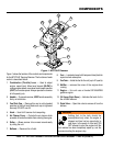
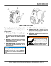
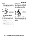
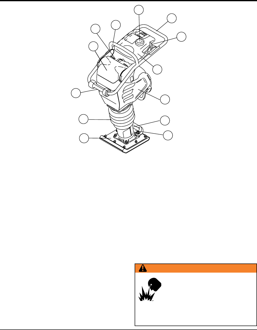
Figure 1. MTX70HF Rammer
2
1
9
3
4
5
6
7
10
11
12
13
8
Figure 1 shows the location of the controls and components
for the MTX70HF Tamping Rammer. The functions of each
control is described below:
1. Combination (Throttle) Lever — Used to adjust
engine speed (rpm). Move lever forward (SLOW) to
reduce engine speed, move lever back toward operator
(FAST) to increase speed. Always operate the rammer
at full speed (rpm).
2. Handle — To operate rammer, GRIP handle assembly
firmly on both sides.
3. Fuel Tank Cap — Remove this cap to add unleaded
gasoline to the fuel tank. Make sure cap is tightened
securely. DO NOT over fill.
4. Hook — Used to lift rammer for transporting.
5. Air Cleaner Cover — Protects the air cleaner which
prevents dirt and other debris from entering the engine.
6. Roller — Allows rammer to be moved around easily
by rolling the unit.
7. Bellows — Reservoir for oil bath.
8.
Foot — Laminated wood with tempered steel plate for
superior shock absorption.
9.
Fuel Tank — Holds the fuel for the unit (up to 2.1quarts).
10. Muffler — reduces the noise of the engine when
running.
11. Engine — this unit uses a Honda GX100UKRB5
gasoline engine.
12.
Oil Gauge (Sight Glass) — Indicates the level of oil in
the oil bath reservoir.
13. Drain Valve — Open this valve to remove oil from the
bellows.
WARNING
Adding fuel to the tank should be
accomplished only when the engine is
stopped and has had an opportunity to
cool down. In the event of a fuel spill, DO
NOT attempt to start the engine until the
fuel residue has been completely wiped up, and the
area surrounding the engine is dry.