


4
If the unit is dc powered, connect the dc supply Positive to the terminal
marked L+ and the dc supply Negative or Common to the terminal
marked N-.
NOTE: On dc powered units, no connection is required to the terminal
marked GND.
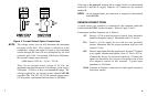
SENSOR CONNECTIONS
A speed sensor (not included) is connected to the terminals under the
section labeled INPUT on the rear panel. Refer to Figure 2 and 3.
Connections and their functions are as follows:
+5V Positive +5 Vdc to provide power to optical, laser, infrared or
amplified magnetic sensors. Maximum load is 75 mA dc.
PX+ Positive +8 Vdc supply for use with two wire proximity
sensors. Maximum load for proper operation with two wire
sensors is 5 mA.
SIG Positive input signal from the speed sensor. Accepts TTL pulses
or ac signals, unipolar and bipolar, from 1.5 Vac to 50 Vac.
(Contact the factory for increased sensitivity.) Connect the
signal wire from three wire sensors or the positive side of two
wire magnetic sensors to this terminal. Typical input
impedance is 10 Kohms.
COM Common or Negative connection for both signal and power
from most sensors.
7
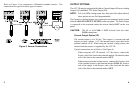
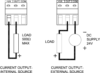
Figure 4 Current Output Option Connections
NOTE: The voltage source you use will determine the maximum
resistance of the load. This voltage is referred to as the
compliance voltage and must be equal to the maximum
current through the load (20 mA) multiplied by the load
resistance, plus 4 Vdc. For example, if the load is 1000 ohms,
the external voltage source must be:
(1000 ohms x 0.020 A) + 4 Vdc = 24 Vdc
Thus, for an external source voltage of 24 Vdc, the
maximum loop load (the sum of all resistances in the loop) is
1000 ohms. 24 Vdc is, in fact, a recommended voltage. The
voltage supplied by an external source should NEVER
exceed 40 Vdc. The ACT-1B 15 Vdc internal voltage source
(+VA) permits a maximum load resistance of 500 ohms.