


3
Installation
Remove the mounting clips, if fitted, and install the unit into the panel from
the front. From the rear of the unit, install the mounting clips on each side
and tighten the mounting screws against the rear of the panel.
WARNING: Do not over tighten the mounting screws.
Power
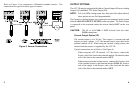
Power to the unit is connected to the terminals under the section labeled
POWER on the rear panel. Be sure the power supplied matches the
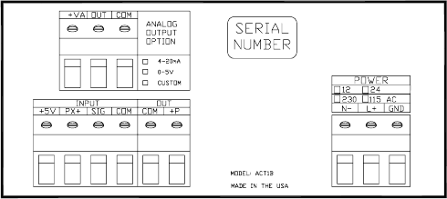
specification indicated on the rear panel. Refer to Figure 2 below.
Figure 2 ACT-1B Rear Panel
If the unit is ac powered (115 Vac or 230 Vac), connect the Live (Hot) wire
to the terminal marked L+ and the Neutral (Return) wire to the terminal
marked N-. Connect the Ground (Earth) wire to the terminal marked GND.
NOTE: For full compliance with CE specifications, the Ground (GND)
connection must be made.
Analog Output Option (AO)
The analog output is 0 to 5 Vdc.
Connect the Positive side of the signal to the terminal marked OUT,
and the Return side of the signal to the terminal marked COM.
NOTE: If your ACT-1B is equipped with either a current output or
an analog output, the full-scale output has been factory preset
to the speed range specified at the time of purchase. The output
is linear in 4096 discrete steps over its designated range.
Pulse Repeater Output Option (PO)
The Pulse Repeater output provides a conditioned TTL positive going
5 V pulse out for each pulse in.
Connect the Positive signal wire (+5 V pulse) to terminal marked +P
and the Return to the terminal marked COM in the rear panel section
labeled OUT.
8