


1
2
1
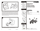
Turn the factory climate control dials into a vertical position and pull the dials off. (see Fig. A).
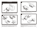
Remove (2) 5/16" hex-head screws securing the temperature and fan control switches and
remove the switches. Unclip the climate control switch and remove the switch. (see Fig. B).
Mount the switches to the back of the Integrated Mounting Kit with (2) #8 x 3/8" Phillips Pan-
head
Screws supplied. (see Fig. C). Holding the climate control dials in a vertical position,
insert the dials onto the posts of the mounted switches and secure. (see Fig. D)
2
ALL VEHICLES
Fig. A
Fig. A
Fig. B
Fig. C
3
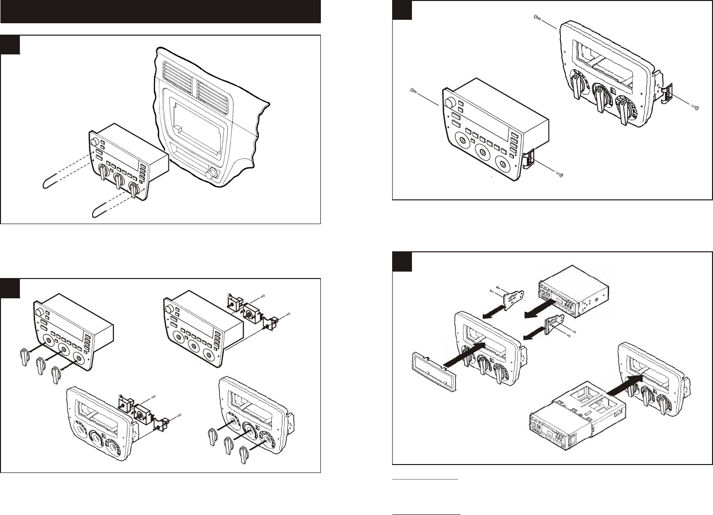
Remove (2) torx-head screws securing the mounting clips to the sides of the factory
radio/climate control panel and remove the clips. (see Fig. A). Mount the clips to the
Integrated
Mounting Kit with the same torx-head screws. (see Fig. B)
4
Fig. B
Fig. B
Disconnect the negative battery terminal to prevent an accidental short circuit. Using Metra's
86-5618,
pull the factory radio/climate control panel from the dash. Disconnect the audio
system connectors, blower motor switch connector, vacuum hose harness, a/c damper door
switch connector, and potentiometer connector. Remove the panel.
Fig. D
ISO HEAD UNITS: Snap the ISO Faceplate into the radio opening. Attach the ISO Brackets
to the inner lip of the radio opening. Slide the head unit into the radio opening, align the holes in
the head unit with the holes in the ISO Brackets and mount the unit to the brackets with the
screws supplied with the unit. (see Fig. A).
DIN
HEAD UNITS: Slide the DIN cage into the Integrated Mounting Kit and secure by
bending the metal locking tabs down. Slide the aftermarket head unit into the cage and
secure. (see Fig. B)
Fig. A