


2
1
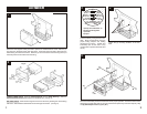
ALL VEHICLES
Disconnect the negative battery terminal to prevent an accidental short circuit. Remove (2)
pop-clips from the sides of the radio trim bezel. Unclip the radio trim bezel, disconnect the
switch wiring and remove the bezel. Remove (2) 7mm hex-head screws securing the top of
the factory head unit and disconnect the wiring.
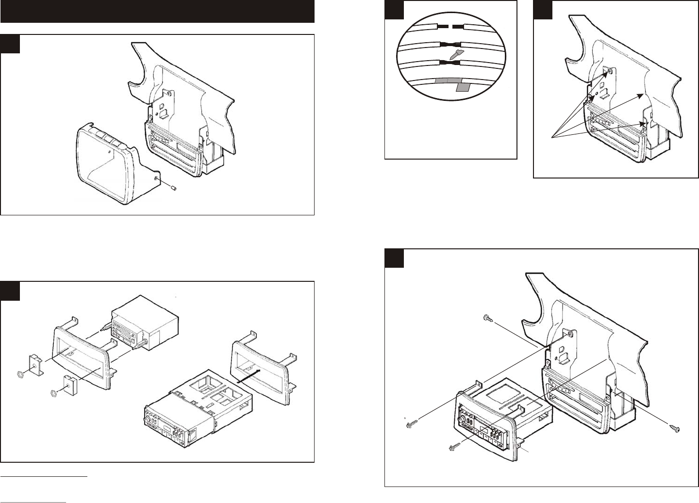
2-SHAFT HEAD UNITS: Snap the Shaft Supports into the Radio Housing. Slide the
aftermarket head unit into the kit and secure with shaft nuts. (see Fig. A)
DIN HEAD UNITS: Slide the DIN cage into the kit and secure by bending the metal locking
tabs down. Slide the aftermarket head unit into the cage until secure. (see Fig. B)
1
Fig. B
2
5
Fig. A
3 4
Locate the factory wiring harness in the
dash. Metra recommends using the
proper mating adaptor and making
connections as shown. (Isolate and
individually tape off the ends of any
unused wires to prevent electrical short
circuit).
Locate the (4) mounting locations in the sub-
dash.
Re-connect the battery terminal and test the unit for proper operation. Mount the head unit/kit
assembly to the sub-dash with (2) 7mm hex-head screws previously removed in step #1 ("A")
and (2) #10 Phillips screws supplied ("B").
A
B
C
D
A) Strip wire ends back ½"
B) Twist ends together
C) Solder
D) Tape
"A"
"B"
"B"
"A"