


2
1
1
ALL VEHICLES
2
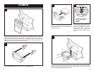
Snap the ISO Brackets over the mounting tabs on the Radio Housing.
3
5
Re-connect the battery terminal and test the unit for proper operation. Mount the head unit/kit
assembly to the sub-dash with (2) Phillips screws previously removed in step #1 ("A") and (2)
#10 x ¾" Phillips Pan-head Screws supplied ("B").
4
Locate the factory wiring harness in the
dash. Metra recommends using the
proper mating adaptor and making
connections as shown. (Isolate and
individually tape off the ends of any
unused wires to prevent electrical short
circuit).
A
B
C
D
A) Strip wire ends back ½"
B) Twist ends together
C) Solder
D) Tape
Slide the head unit into the Radio Housing, align
the holes in the head unit with the holes in the
Housing and mount the unit with the screws
supplied with the unit.
"A"
"A"
"B"
"B"
Disconnect the negative battery terminal to prevent an accidental short circuit. Detach the
cable located under the left side of the glove box. Unclip the trim piece in front of the gear
shifter and remove (2) Phillips screws exposed. Unclip the gear shifter trim and remove (2)
Phillips screws exposed. Unclip the radio trim bezel and remove. Remove (6) Phillips screws
securing the factory head unit and disconnect the wiring.