


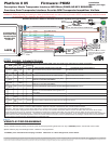
Platform # 05 Firmware: PKM2
Description: Mazda Transponder Interface: MPV/Miata (PKM2) NO KEY REQUIRED
Functions: Data Transponder Interface: Override OEM Transponder Immobilizer Via Data
Downloadable Firmware for Platform #05: PKG3,PKG8,PKH1, PKH2,PKH3,PKH4,PKHY1,PKM2,PKN2,PKT2
WARNING: Before beginning your install go to www.XpressDownload.com and be sure to print the LATEST corresponding installation manual
for the firmware that is flashed to the platform you are using.
Installation
Manual (1\1 Page)
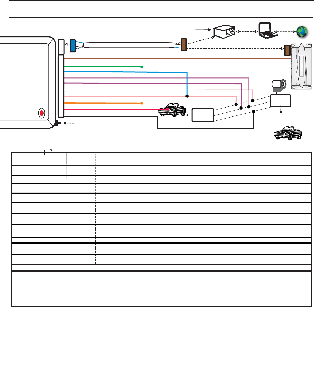
Red
Green
Blue
Violet
Black
Violet/White
Pink
Pink/White
Chassis Ground
(+)12 Volt Constant
Brown
Ground When Running
D2D
10 PIN HARNESS
INPUT
INPUT
INPUT
DATA
(-)
(+)
(-)
4 PIN DATA TO DATA(D2D) CABLE (OPTIONALACCESSORY)
Data (ECM Side)
See Wire Connection Guide for detailed information regarding wire functionality
P.C.
USB Adaptor
USB Cable
Option A
Firmware Upgrades
Blue
Brown
CLEARCODE VIP
DATA PORT
OptionB-Data2DataConnection to RCS Data Port
Section A
N/C
N/CN/C
Ignition (ECM Side)
Orange
LED
Programming
button
D2D
RC SEMOTE ONTROL YSTEM
KEYLESS / STARTER/ ALARM
RCS
Internet
Section B
OUTPUT
(+)
(+)
N/C
DATA to DATA PORT (D2D):
of D2D Cable plugs into the upgradeable vehicle interface module.
OPTION A: - D2D Port used to connect to USB Bootloader adaptor & computer to download & flash vehicle interface firmware.
OPTION B: - D2D Port used to connect to the data port of a remote control system equipped with ClearCode ehicle nterface rotocol.
Remote control systems designed with ClearCode VIP can securely communicate via the D2D cable to transmit & receive data commands which initiate
specific vehicle function such as doorlocks & immobilizer override and /or request information from the vehicle such as status of entry points (doors)or
ambiant température, diesel glow plug etc… ClearCode VIP represents the doorway to vehicle integration...As an enhanced security feature, this upgradeable
vehicle interface module automatically detects when the Vehicle Interface Protocol is present and deactivates the analogue override input wire (brown wire)
ensuring that this module can only be activated by an authorized user.
VI P
Blue connector
Legend RCS = Remote Control System N/C = No Connection N/A = Not Applicable W2W= analogue wire to wire D2D= data 2 data
(-)
/(+)
(-)
Input
Input
Input
Data
I/O
STATUS
WIRE
COLOR
Brown
Green
Blue
Violet/
White
Violet
Pink/
White
Pink
Orange
Red
Black
(-)
(+)
SPECIFIC WIRE CONNECTION LOCATION
Constant (+) 12 Volt Source
Connect to Black or Black/Orange Vehicle Ground wire
Connect
Location
Vehicle
Vehicle
Vehicle
ACTIVATION and/or FUNCTIONALITY
RCS
Power Source
Ground Source
WIRE GUIDE: CONNECTIONS
Data Commands from Module to Vehicle
PIN#
1
2
3
4
5
6
7
8
9
10
Ground When Running output of remote starter
10 PIN HARNESS
D2D
w2w
D2D = Optional use of 4 Pin Data to Data (D2D) cable will replace the analogue wire (w2w) connection
D2D
w2w
w2w
w2w
w2w
D2D
w2w
D2D
w2w
w2w
Output
N/C
N/C
N/CN/C
N/C
N/C
Vehicle
Vehicle
(+)
(+)
Output
Immobilizer Bypass Via Data
Connect in parallel to Pink wire of 10 PIN Harness
ThisInterfacekit /DataBusInterfaceparthasbeentestedonthe listedvehicles.Othervehicleswillbeaddedtotheselect vehiclelistuponcompletionofcompatibilitytesting.Visitwebsiteforlatestvehicle applicationguide. :Undernocircumstances shall
themanufacturerorthedistributorsofthebypasskit/ databusinterfacepart(s)be held liableforany consequentialdamagessustainedinconnection withthepart(s)installation.Themanufacturer andit’sdistributorswillnot,norwillthey authorizeany representativeor
anyotherindividualtoassumeobligationorliabilityin relationtotheinterfacekit /databusinterfacepart(s) otherthanitsreplacement.
DISCLAIMER
N.B.:Undernocircumstancesshallthemanufactureranddistributorsof thisproductareliablefor consequentialdamagessustainedin
connectionwiththisproductneitherassumesnorauthorizesanyrepresentativeorotherpersontoassumeforitanyobligationorliabilityotherthanthereplacementofthisproductonly.
Ignition ECM Side
INPUT
OUTPUT
(+)
(+)
Input
Vehicle
N/C
Connect to Blue/Black Vehicle Data wire (ECM Side)
*Data wire in the Miata is Red/Black
Connect to Black/White Vehicle Ignition wire (Key Side)
Once connected in parallel to Blue wire of 10 PIN
harness, connect to Black/White Vehicle Ignition wire
(ECM Side)
Ignition Power Source Supply
Ignition Power Source Supply
Ignition Power Source Return
N/C
DATA
ECM
Side
MAZDA
IMMOBILIZER
MODULE
Black/White
Blue/Black
Black or Black/Orange
Ignition
Data
Ground
Immobilizer module is located
under dash on the driver side
to the right of the steering
column.
Key
Side
N/C N/C N/C N/C N/C N/C
w2w
Data
Vehicle
Connect to Blue/Black Vehicle Data wire (Key Side)
*Data wire in the Miata is Red/Black
Data Commands from Module to Vehicle
VEHICLE PROGRAMMING
Section C
1) IGNITION
2)
Once module has been properly connected, press and hold programming button then turn key to position, LED should come on solid.
Start vehicle by key, LED will begin to flash. Module is now programmed.
*To RESET, press and hold button and plug in module. LED comes on. When LED goes off, release button.
UPGRADEABLE
OVERRIDE OEM
TRANSPONDER
IMMOBILIZER
VIA DATA
Data (Key Side)
Ignition (Key Side)
B
B