POWER CONNECTION
Insert the small DC plug 1. (figure 10) of the power cable into the right side
of the monitor (figure 12).
Insert the larger 12 Volt power plug 2. (figure 10) into the vehicle power socket.
The red LED (figure 11) will come on if the vehicle socket has power.
Notice: Depending on the make/model of the vehicle the ignition may
need to be turned on or to the accessory position for the 12V socket
to have power.
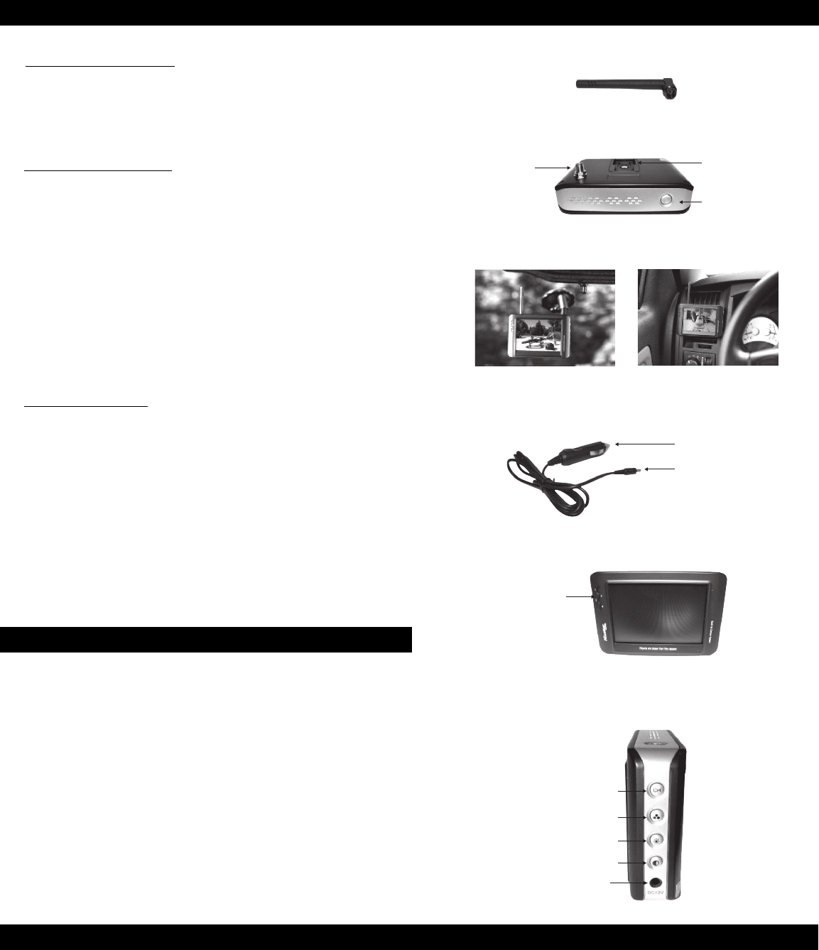
MOUNTING THE MONITOR
When choosing a location to mount the monitor (figure 7), make sure the monitor
is in an area that will not obstruct your vision while driving or interfere with access
to any of the vehicle controls. It can be placed on the windshield using the mounting
arm (figure 8) or clipped to an air vent (figure 9). Both options use the mounting slot
(figure 7) on the back of the monitor.
Temporarily place the monitor stand or clip in the location that you have chosen 1.
and route the power cable (figure 10) to the vehicle’s 12V power outlet and verify
the cable does not interfere with the safe operation of the vehicle or access to
any vehicle controls.
To use the mounting arm, slide it into the mounting slot 2. (figure 7) and remove the
vinyl protector from the base, place it firmly on a smooth surface and rotate the
small cam near the base of the arm.
To use the vent clip, slide it into the monitor mounting slot 3. (figure 7) and gently
press the clip and monitor over the vehicle air vent fins.
1. Turn the vehicle ignition to the accessory position.
Do not start the vehicle.
2. Turn on the monitor and the blue status LED should come on.
3. If there is no picture on the display.
a. Set the monitor to channel 4 if needed.
b. Turn on the vehicle lights.
4. Adjust the monitor antenna for the best picture.
Testing the System:
Notice: Re-locating the monitor even a small amount inside the vehicle can affect
the picture quality. This device, as well as all other wireless devices, may be subject
to interference caused by cell phones, Bluetooth headsets, Wi-Fi routers, power lines
and other various electrical equipment, including other cameras.
Figure 11
Power and
Channel LED
Indicator
3.5" LCD TFT Display, 480x243
Power Cable
Figure 10
12 Volt Power Plug
DC Plug
Controls:
Blue LED Power and Wireless Channel Indicator (figure 11) - When the monitor
is ON the blue LED will be lit. The location of the blue LED also indicates what channel
the display is set to display.
Power Button (figure 7)- Press the Power button to turn the display ON, the blue
LED will be lit to indicate the monitor is ON. Press it again to turn the display OFF,
the blue LED will turn off.
Wireless Channel (figure 12) – This display can accept 4 different channels of
wireless transmission. To change the channel press the “CH” button and it will
go to the next channel after channel 4 it will return to channel 1. The camera is
pre-set to channel 4.
Brightness (figure 12) - There are 6 levels of brightness. To adjust the brightness,
press the Brightness Control button. Press the button to increase the brightness,
after the highest level it will return to the lowest level.
Contrast Control (figure 12) - There are 6 levels of contrast. To adjust the contrast,
press the Contrast Control button. Press the button to increase the contrast, after
the highest level it will return to the lowest level.
Notice: Under extreme bright light conditions, the screen image may
take a few seconds to automatically adjust. It is best to wait until the
image has stabilized before backing up.
Connecting the Monitor and Antenna:
ATTACHING THE ANTENNA
The wireless antenna (figure 6) attaches to the threaded connector on
the back of the monitor (figure 7). Once attached, it can be rotated 360°
as needed to find the position which give the best reception from the camera.
Figure 6
Figure 7
Threaded Wireless
Antenna Connector
Mounting Slot
Power Button
(On/Off)
Figure 12
Contrast
No Function
Brightness
Wireless Channel
DC Input
Mounting Arm Vent Clip
Figure 8 Figure 9


