


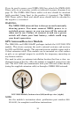
30
CAUTION:
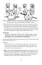
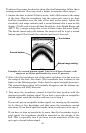
If you drill a hole in the transom for the cable, make sure it is
located above the waterline. After installation, be sure to seal the
hole with the same marine grade above- or below-waterline seal-
ant used for the screws.
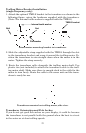
The sensor is now ready for use. Connect the sensor to the sonar socket
on the back of your unit and connect the transducer to the speed sen-
sor's socket. If you have any questions concerning the installation of
the sensor, please contact your local boat dealer.
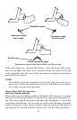
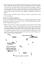
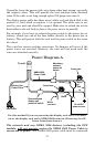
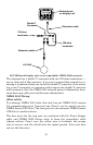
Power Connections
Your unit comes with a power/data cable that splits into three
branches, each with several exposed wires.
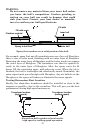
The thicker three-wire cable (white, red and black) is the power supply
for your display unit. This cable has no label.
The thinner branch with three wires (red, black and shield) is the
power cable for a NMEA 2000 network. It is labeled "NMEA 2000
POWER."
The branch with four wires (blue, yellow, orange, and shield) is a data
cable, labeled "RS-232 COMM." It supports a serial communication
port. This allows your unit to exchange NMEA 0183 data with another
device, such as an autopilot, DSC marine radio or computer.
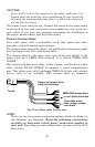
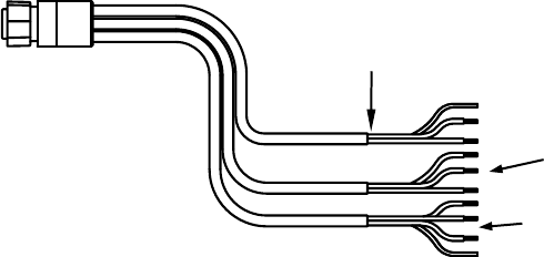
The Power/Data cable for this unit.
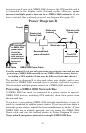
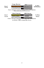
NOTE:
There are two basic power connection options, which are shown in
the following two diagrams. Read the following instructions
carefully to determine which power connection applies to
your unit. Depending on your configuration, you may not use all of
these wires.
To unit
Display unit power wires:
white, red and black
NMEA 2000 power wires:
red, black and shield
Data cable wires:
blue, yellow, orange,
and shield